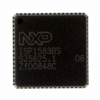
ISP1583BSUM ST-Ericsson Inc, ISP1583BSUM Datasheet - Page 57

ISP1583BSUM
Manufacturer Part Number
ISP1583BSUM
Description
IC USB PERIPH CONTROLLER 64HVQFN
Manufacturer
ST-Ericsson Inc
Datasheet
1.ISP1583BSUM.pdf
(100 pages)
Specifications of ISP1583BSUM
Controller Type
USB Peripheral Controller
Interface
Parallel/Serial
Voltage - Supply
3 V ~ 3.6 V
Current - Supply
47mA
Operating Temperature
-40°C ~ 85°C
Mounting Type
Surface Mount
Package / Case
64-VQFN Exposed Pad, 64-HVQFN, 64-SQFN, 64-DHVQFN
Lead Free Status / RoHS Status
Lead free / RoHS Compliant
Other names
568-1886-2
ISP1583BS,518
ISP1583BS-T
ISP1583BS,518
ISP1583BS-T
Available stocks
Company
Part Number
Manufacturer
Quantity
Price
Company:
Part Number:
ISP1583BSUM
Manufacturer:
MICRON
Quantity:
2 000
Company:
Part Number:
ISP1583BSUM
Manufacturer:
ST-ERICS
Quantity:
829
Part Number:
ISP1583BSUM
Manufacturer:
STE
Quantity:
20 000
NXP Semiconductors
Table 72.
ISP1583_7
Product data sheet
Bit
Symbol
Reset
Bus reset
Access
Bit
Symbol
Reset
Bus reset
Access
DMA Interrupt Reason register: bit allocation
9.4.6 DMA Interrupt Reason register (address: 50h)
TEST3
15
R
0
0
7
-
-
-
This 2-byte register shows the source(s) of DMA interrupt. Each bit is refreshed after a
DMA command is executed. An interrupt source is cleared by writing logic 1 to the
corresponding bit. On detecting the interrupt, the external microprocessor must read the
DMA Interrupt Reason register and mask it with the corresponding bits in the DMA
Interrupt Enable register to determine the source of the interrupt.
The bit allocation is given in
Table 73.
Bit
15
14 to 13
12
11
10
9
8
7 to 5
4
3
reserved
14
6
-
-
-
-
-
-
Symbol
TEST3
-
GDMA_STOP
EXT_EOT
INT_EOT
INTRQ_
PENDING
DMA_XFER_OK
-
READ_1F0
BSY_DONE
reserved
DMA Interrupt Reason register: bit description
13
5
-
-
-
-
-
-
Rev. 07 — 22 September 2008
READ_1F0
Table
Description
This bit is set when a DMA transfer for a packet (OUT transfer)
terminates before the whole packet is transferred. This bit is a
status bit, and the corresponding mask bit of this register is always
0. Writing any value other than 0 has no effect.
reserved
GDMA Stop: When the GDMA_STOP command is issued to DMA
Command registers, it means the DMA transfer has successfully
terminated.
External EOT: Logic 1 indicates that an external EOT is detected.
This is applicable only in GDMA slave mode.
Internal EOT: Logic 1 indicates that an internal EOT is detected;
see
Interrupt Pending: Logic 1 indicates that a pending interrupt was
detected on pin INTRQ.
DMA Transfer OK: Logic 1 indicates that the DMA transfer is
completed (DMA Transfer Counter has become zero). This bit is
only used in GDMA (slave) mode and MDMA (master) mode.
reserved
Read 1F0: Logic 1 indicates that the 1F0 FIFO contains unread
data and the microcontroller can start reading data.
Busy Done: Logic 1 indicates that the BSY status bit has become
zero and polling has been stopped.
GDMA_
STOP
R/W
R/W
12
Table
0
0
4
0
0
72.
74.
EXT_EOT
DONE
BSY_
R/W
R/W
11
0
0
3
0
0
Hi-Speed USB peripheral controller
INT_EOT
TF_RD_
DONE
R/W
R/W
10
0
0
2
0
0
INTRQ_OK
PENDING
INTRQ_
CMD_
R/W
R/W
9
0
0
1
0
0
© NXP B.V. 2008. All rights reserved.
ISP1583
XFER_OK
reserved
DMA_
R/W
8
0
0
0
-
-
-
56 of 99


