PIC18F65K90-I/MR Microchip Technology, PIC18F65K90-I/MR Datasheet - Page 201
PIC18F65K90-I/MR
Manufacturer Part Number
PIC18F65K90-I/MR
Description
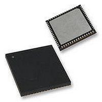
32kB Flash, 2kB RAM, 1kB EE, NanoWatt XLP, LCD 64 QFN 9x9x0.9mm TUBE
Manufacturer
Microchip Technology
Series
PIC® XLP™ 18Fr
Datasheet
1.PIC18F65K90-IMR.pdf
(570 pages)
Specifications of PIC18F65K90-I/MR
Processor Series
PIC18F
Core
PIC
Data Bus Width
8 bit
Program Memory Type
Flash
Program Memory Size
32 KB
Data Ram Size
2 KB
Interface Type
I2C, SPI
Maximum Clock Frequency
64 MHz
Number Of Timers
8
Operating Supply Voltage
1.8 V to 5.5 V
Maximum Operating Temperature
+ 125 C
3rd Party Development Tools
52715-96, 52716-328, 52717-734, 52712-325, EWPIC18
Minimum Operating Temperature
- 40 C
On-chip Adc
12 bit, 16 Channel
Core Processor
PIC
Core Size
8-Bit
Speed
64MHz
Connectivity
I²C, LIN, SPI, UART/USART
Peripherals
Brown-out Detect/Reset, LCD, POR, PWM, WDT
Number Of I /o
53
Eeprom Size
1K x 8
Ram Size
2K x 8
Voltage - Supply (vcc/vdd)
1.8 V ~ 5.5 V
Data Converters
A/D 16x12b
Oscillator Type
Internal
Operating Temperature
-40°C ~ 85°C
Package / Case
64-VFQFN Exposed Pad
Lead Free Status / Rohs Status
Details


15.0
The Timer3/5/7 timer/counter modules incorporate
these features:
• Software-selectable operation as a 16-bit timer or
• Readable and writable 8-bit registers (TMRxH
• Selectable clock source (internal or external) with
• Interrupt-on-overflow
• Module Reset on ECCP Special Event Trigger
Timer7 is unimplemented for devices with a program
memory of 32 Kbytes (PIC18FX5K90).
2009-2011 Microchip Technology Inc.
counter
and TMRxL)
device clock or SOSC oscillator internal options
Note: Throughout this section, generic references
TIMER3/5/7 MODULES
are used for register and bit names that are the
same, except for an ‘x’ variable that indicates
the item’s association with the Timer3, Timer5
or Timer7 module. For example, the control
register is named TxCON and refers to
T3CON, T5CON and T7CON.
PIC18F87K90 FAMILY
A simplified block diagram of the Timer3/5/7 module is
shown in
The Timer3/5/7 module is controlled through the
TxCON register
clock source options for the ECCP modules. (For more
information, see
Timer
The F
ECCP capture/compare features. If the timer will be
used with the capture or compare features, always
select one of the other timer clocking options.
OSC
Resources”.)
Figure
clock source should not be used with the
15-1.
Section 19.1.1 “ECCP Module and
(Register
15-1). It also selects the
DS39957D-page 201
Related parts for PIC18F65K90-I/MR
Image
Part Number
Description
Manufacturer
Datasheet
Request
R

Part Number:
Description:
Manufacturer:
Microchip Technology Inc.
Datasheet:
Part Number:
Description:
Manufacturer:
Microchip Technology Inc.
Datasheet:
Part Number:
Description:
Manufacturer:
Microchip Technology Inc.
Datasheet:
Part Number:
Description:
Manufacturer:
Microchip Technology Inc.
Datasheet:
Part Number:
Description:
Manufacturer:
Microchip Technology Inc.
Datasheet:
Part Number:
Description:
Manufacturer:
Microchip Technology Inc.
Datasheet:
Part Number:
Description:
Manufacturer:
Microchip Technology Inc.
Datasheet:
Part Number:
Description:
Manufacturer:
Microchip Technology Inc.
Datasheet: