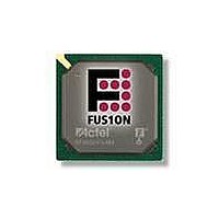
AFS250-FGG256 Actel, AFS250-FGG256 Datasheet - Page 52

AFS250-FGG256
Manufacturer Part Number
AFS250-FGG256
Description
FPGA - Field Programmable Gate Array 250K System Gates
Manufacturer
Actel
Datasheet
1.AFS600-PQG208.pdf
(330 pages)
Specifications of AFS250-FGG256
Processor Series
AFS250
Core
IP Core
Maximum Operating Frequency
1098.9 MHz
Number Of Programmable I/os
114
Data Ram Size
36864
Supply Voltage (max)
1.575 V
Maximum Operating Temperature
+ 70 C
Minimum Operating Temperature
0 C
Development Tools By Supplier
AFS-Eval-Kit, AFS-BRD600, FlashPro 3, FlashPro Lite, Silicon-Explorer II, Silicon-Sculptor 3, SI-EX-TCA
Mounting Style
SMD/SMT
Supply Voltage (min)
1.425 V
Number Of Gates
250 K
Package / Case
FPBGA-256
Lead Free Status / RoHS Status
Lead free / RoHS Compliant
Available stocks
Company
Part Number
Manufacturer
Quantity
Price
Company:
Part Number:
AFS250-FGG256
Manufacturer:
Actel
Quantity:
135
Company:
Part Number:
AFS250-FGG256
Manufacturer:
ACTEL
Quantity:
6 800
Company:
Part Number:
AFS250-FGG256I
Manufacturer:
Microsemi SoC
Quantity:
10 000
- Current page: 52 of 330
- Download datasheet (13Mb)
Device Architecture
2- 36
Example: Calculation for Match Count
To put the Fusion device on standby for one hour using an external crystal of 32.768 KHz:
The period of the crystal oscillator is T
The period of the counter is T
The Match Count for 1 hour is Δtmatch:
Δtmatch / T
Using a 32.768 KHz crystal, the maximum standby time of the 40-bit counter is 4,294,967,296 seconds,
which is 136 years.
Table 2-16 • RTC Control/Status Register
Bit
7
6
5
4:3
2
1
0
T
T
crystal
counter
xt_mode[1:0]
rst_cnt_omat
vr_en_mat
= 1 / 32.768 KHz = 30.518 µs
rstb_cnt
cntr_en
counter
xtal_en
= 30.518 us X 128 = 3.90625 ms
rtc_rst
Name
= (1 hr X 60 min/hr X 60 sec/min) / 3.90625 ms = 921600 or 0xE1000
RTC Reset
1 – Resets the RTC
0 – Deassert reset on after two ACM_CLK cycle.
Counter Enable
1 – Enables the counter; rtc_rst must be deasserted as well. First
counter increments after 64 RTCCLK positive edges.
0 – Disables the crystal prescaler but does not reset the counter
value. Counter value can only be updated when the counter is
disabled.
Voltage Regulator Enable on Match
1 – Enables RTCMATCH and RTCPSMMATCH to output 1 when the
counter value equals the Match Register value. This enables the 1.5 V
voltage
RTCPSMMATCH signal in VRPSM.
0 – RTCMATCH and RTCPSMMATCH output 0 at all times.
Crystal Mode
Controls RTCXTLMODE[1:0]. Connects to RTC_MODE signal in
XTLOSC. XTL_MODE uses this value when xtal_en is 1. See the
"Crystal Oscillator" section on page 2-21
Reset Counter on Match
1 – Enables the sync clear of the counter when the counter value
equals the Match Register value. The counter clears on the rising
edge of the clock. If all the Match Registers are set to 0, the clear is
disabled.
0 – Counter increments indefinitely
Counter Reset, active Low
0 - Resets the 40-bit counter value
Crystal Enable
Controls RTCXTLSEL. Connects to SELMODE signal in XTLOSC.
0 – XTLOSC enables control by FPGA_EN; xt_mode is not used.
Sleep mode requires this bit to equal 0.
1 – Enables XTLOSC, XTL_MODE control by xt_mode
Standby mode requires this bit to be set to 1.
See the
SELMODE configuration.
counter
"Crystal Oscillator" section on page 2-21
regulator
:
crystal
:
R e visio n 1
when
Description
RTCPSMMATCH
for mode configuration.
for further details on
connects
to
the
Default
Value
00
0
0
0
0
0
Related parts for AFS250-FGG256
Image
Part Number
Description
Manufacturer
Datasheet
Request
R

Part Number:
Description:
FPGA 256/I°/Fusion Voltage: 1.5, 1.8, 2.5, 3.3 Mixed Voltage
Manufacturer:
Actel
Datasheet:

Part Number:
Description:
FPGA - Field Programmable Gate Array 250K System Gates
Manufacturer:
Actel
Datasheet:

Part Number:
Description:
MCU, MPU & DSP Development Tools Silicon Sculptor Programming Mod
Manufacturer:
Actel

Part Number:
Description:
MCU, MPU & DSP Development Tools InSystem Programming ProASICPLUS Devices
Manufacturer:
Actel

Part Number:
Description:
Programming Socket Adapters & Emulators PQ160 Module
Manufacturer:
Actel

Part Number:
Description:
Programming Socket Adapters & Emulators Axcelerator Adap Module Kit
Manufacturer:
Actel

Part Number:
Description:
Programming Socket Adapters & Emulators Evaluation
Manufacturer:
Actel

Part Number:
Description:
Programming Socket Adapters & Emulators AFDX Solutions
Manufacturer:
Actel

Part Number:
Description:
Programming Socket Adapters & Emulators SILICON SCULPTOR ADAPTER MODULE
Manufacturer:
Actel
Datasheet:

Part Number:
Description:
Programming Socket Adapters & Emulators Axcelerator Adap Module Kit
Manufacturer:
Actel

Part Number:
Description:
Programming Socket Adapters & Emulators Evaluation
Manufacturer:
Actel

Part Number:
Description:
Programming Socket Adapters & Emulators Silicon Sculptor Software
Manufacturer:
Actel

Part Number:
Description:
Programming Socket Adapters & Emulators InSystem Programming ProASICPLUS Devices
Manufacturer:
Actel


