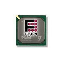
AFS250-FGG256 Actel, AFS250-FGG256 Datasheet - Page 228

AFS250-FGG256
Manufacturer Part Number
AFS250-FGG256
Description
FPGA - Field Programmable Gate Array 250K System Gates
Manufacturer
Actel
Datasheet
1.AFS600-PQG208.pdf
(330 pages)
Specifications of AFS250-FGG256
Processor Series
AFS250
Core
IP Core
Maximum Operating Frequency
1098.9 MHz
Number Of Programmable I/os
114
Data Ram Size
36864
Supply Voltage (max)
1.575 V
Maximum Operating Temperature
+ 70 C
Minimum Operating Temperature
0 C
Development Tools By Supplier
AFS-Eval-Kit, AFS-BRD600, FlashPro 3, FlashPro Lite, Silicon-Explorer II, Silicon-Sculptor 3, SI-EX-TCA
Mounting Style
SMD/SMT
Supply Voltage (min)
1.425 V
Number Of Gates
250 K
Package / Case
FPBGA-256
Lead Free Status / RoHS Status
Lead free / RoHS Compliant
Available stocks
Company
Part Number
Manufacturer
Quantity
Price
Company:
Part Number:
AFS250-FGG256
Manufacturer:
Actel
Quantity:
135
Company:
Part Number:
AFS250-FGG256
Manufacturer:
ACTEL
Quantity:
6 800
Company:
Part Number:
AFS250-FGG256I
Manufacturer:
Microsemi SoC
Quantity:
10 000
- Current page: 228 of 330
- Download datasheet (13Mb)
Device Architecture
Table 2-166 • AC Waveforms, Measuring Points, and Capacitive Loads
Table 2-167 • LVDS
Figure 2-133 • BLVDS/M-LVDS Multipoint Application Using LVDS I/O Buffers
2- 21 2
Input Low (V)
1.075
Note:
Speed Grade
Note:
Std.
–1
–2
R
T
Z
Z
Z
*Measuring point = V
For the derating values at specific junction temperature and voltage supply levels, refer to
page
stub
0
0
Receiver
+
Commercial Temperature Range Conditions: T
Worst-Case VCCI = 2.3 V
Applicable to Pro I/Os
R
BLVDS/M-LVDS
Bus LVDS (BLVDS) and Multipoint LVDS (M-LVDS) specifications extend the existing LVDS standard to
high-performance multipoint bus applications. Multidrop and multipoint bus configurations can contain
any combination of drivers, receivers, and transceivers. Actel LVDS drivers provide the higher drive
current required by BLVDS and M-LVDS to accommodate the loading. The driver requires series
terminations for better signal quality and to control voltage swing. Termination is also required at both
ends of the bus, since the driver can be located anywhere on the bus. These configurations can be
implemented using TRIBUF_LVDS and BIBUF_LVDS macros along with appropriate terminations.
Multipoint designs using Actel LVDS macros can achieve up to 200 MHz with a maximum of 20 loads. A
sample application is given in
section in
Example: For a bus consisting of 20 equidistant loads, the following terminations provide the required
differential voltage, in worst-case industrial operating conditions at the farthest receiver: R
R
R
3-9.
S
T
-
= 70 Ω, given Z
EN
Timing Characteristics
R
Z
S
stub
Table
Z
Z
Z
0
0
stub
Transceiver
trip
2-168.
+
R
. See
T
t
0
S
DOUT
0.66
0.56
0.49
= 50 Ω (2") and Z
-
EN
R
Z
stub
S
Table 2-87 on page 2-168
Z
Z
Z
0
0
Figure
Input High (V)
stub
Driver
+
1.325
R
D
S
2-133. The input and output buffer delays are available in the LVDS
2.10
1.79
1.57
stub
-
t
EN
DP
R
Z
S
stub
= 50 Ω (~1.5").
R e visio n 1
Z
Z
Z
0
0
stub
J
for a complete table of trip points.
= 70°C, Worst-Case VCC = 1.425 V,
Receiver
+
R
R
S
0.04
0.04
0.03
-
t
EN
DIN
R
Z
S
stub
Measuring Point* (V)
Cross point
...
Z
Z
0
0
1.82
1.55
1.36
t
Transceiver
PY
+
R
T
S
-
EN
R
S
V
REF
BIBUF_LVDS
Table 3-7 on
S
Z
Z
Units
0
0
(typ.) (V)
= 60 Ω and
–
ns
ns
ns
R
T
Related parts for AFS250-FGG256
Image
Part Number
Description
Manufacturer
Datasheet
Request
R

Part Number:
Description:
FPGA 256/I°/Fusion Voltage: 1.5, 1.8, 2.5, 3.3 Mixed Voltage
Manufacturer:
Actel
Datasheet:

Part Number:
Description:
FPGA - Field Programmable Gate Array 250K System Gates
Manufacturer:
Actel
Datasheet:

Part Number:
Description:
MCU, MPU & DSP Development Tools Silicon Sculptor Programming Mod
Manufacturer:
Actel

Part Number:
Description:
MCU, MPU & DSP Development Tools InSystem Programming ProASICPLUS Devices
Manufacturer:
Actel

Part Number:
Description:
Programming Socket Adapters & Emulators PQ160 Module
Manufacturer:
Actel

Part Number:
Description:
Programming Socket Adapters & Emulators Axcelerator Adap Module Kit
Manufacturer:
Actel

Part Number:
Description:
Programming Socket Adapters & Emulators Evaluation
Manufacturer:
Actel

Part Number:
Description:
Programming Socket Adapters & Emulators AFDX Solutions
Manufacturer:
Actel

Part Number:
Description:
Programming Socket Adapters & Emulators SILICON SCULPTOR ADAPTER MODULE
Manufacturer:
Actel
Datasheet:

Part Number:
Description:
Programming Socket Adapters & Emulators Axcelerator Adap Module Kit
Manufacturer:
Actel

Part Number:
Description:
Programming Socket Adapters & Emulators Evaluation
Manufacturer:
Actel

Part Number:
Description:
Programming Socket Adapters & Emulators Silicon Sculptor Software
Manufacturer:
Actel

Part Number:
Description:
Programming Socket Adapters & Emulators InSystem Programming ProASICPLUS Devices
Manufacturer:
Actel


