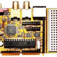
Chameleon-PIC Nurve Networks, Chameleon-PIC Datasheet - Page 71

Chameleon-PIC
Manufacturer Part Number
Chameleon-PIC
Description
MCU, MPU & DSP Development Tools PIC24 & PROPELLER DEV SYSTEM (SBC)
Manufacturer
Nurve Networks
Datasheet
1.CHAMELEON-PIC.pdf
(263 pages)
Specifications of Chameleon-PIC
Processor To Be Evaluated
PIC24
Data Bus Width
16 bit
Interface Type
USB, VGA, PS/2, I2C, ISP, SPI
Operating Supply Voltage
3.3 V, 5 V
Lead Free Status / RoHS Status
Lead free / RoHS Compliant
- Current page: 71 of 263
- Download datasheet (12Mb)
Filters can be a lot of fun since you can chain them together; low pass, high pass to make a band pass, or multiple low
and high pass to make them fall off faster and so forth. Here’s a cool tool on the web to get a “feel” for filters:
In any event, playing with the math, the 3dB point for our circuit is:
Notice, f is not in there since we solved for it. Therefore, we have everything we need to use the circuit and the equation.
Let R and C in our circuit be 1K Ohm and 0.1uF respectively, plugging them in we get:
Which might be a little low, to loosen this up, let’s make the resistor smaller – 200 Ohm:
Which is a rather high frequency about 50% the max range of most human ears which top out at 15-20KHz.
Why is this important? Well, first off if you send a signal thru our little low pass filter to the output (connected to the audio
port on the TV) then the signal is going to attenuate at high frequencies. We will get back to this momentarily, let’s move
on to the second stage in the audio circuit which is based on C15. This stage of the circuit is a AC pass filter, that means
that it will only pass AC and the DC component will be blocked. In other words, say that the input was a sine wave or
square or square wave with a peak to peak voltage of 1V, but it was riding on a 2V signal, this would look like Figure 14.2
(top graph in blue). However, after going thru the AC coupling capacitor, the signal would look like that shown in Figure
14.2 (bottom graph in red). So all C15 does is block the DC. Now, let’s talk about the some more hardware related
concepts about making sounds with a couple specific techniques used for many of the Propeller audio drivers. Of course,
you don’t need to know this material since you are simply going to use a driver someone else writes (like the default
drivers we provide), however, it can’t hurt to have an understanding of how the sounds are generated typically by these
drivers.
14.1.1 Pulse Code Modulation (PCM)
The most common method to make sound on a game console is to use PCM or Pulse Code Modulation. This is really
nothing more than storing a series of samples of the sound in some resolution; 4,8,12,16 bit along at some playback rate.
A .WAVE file for example is PCM data, you simply output the data at the proper rate to a D/A converter with an amplifier
connected to a speaker and you will hear the sound. There are a number of issues with this; first it takes huge amounts of
memory (even with compression), secondly you need a D/A (digital to analog) converter on the hardware and there is no
“synthesis “ opportunities really (of course you can always synthesis the samples). PCM is a viable option for the
Chameleon PIC, but there is so little FLASH memory (relatively speaking) you would have to stream off and external SD
Low Pass: http://www.st-andrews.ac.uk/~www_pa/Scots_Guide/experiment/lowpass/lpf.html
High Pass: http://www.st-andrews.ac.uk/~www_pa/Scots_Guide/experiment/highpass/hpf.html
f
f
f
3dB
3dB
3dB
Figure 14.2 – Sine wave riding on a constant DC offset as its passed thru a coupling capacitor.
= 1/(2*PI*RC)
= 1/(2*PI*1K*0.1uF) = 1.59 KHz
= 1/(2*PI*200*0.1uF) = 7.95 KHz
© 2009 NURVE NETWORKS LLC “Exploring the Chameleon PIC 16-Bit”
71
Related parts for Chameleon-PIC
Image
Part Number
Description
Manufacturer
Datasheet
Request
R

Part Number:
Description:
MCU, MPU & DSP Development Tools AVR8 VIDEO GAME DEV SYSTEM (SBC)
Manufacturer:
Nurve Networks

Part Number:
Description:
MCU, MPU & DSP Development Tools PIC24 VIDEO GAME DEV SYSTEM (SBC)
Manufacturer:
Nurve Networks

Part Number:
Description:
MCU, MPU & DSP Development Tools AVR8 & PROPELLER DEV SYSTEM (SBC)
Manufacturer:
Nurve Networks
Datasheet:


