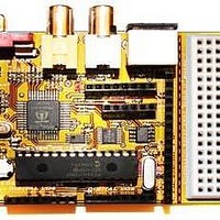
Chameleon-PIC Nurve Networks, Chameleon-PIC Datasheet - Page 156

Chameleon-PIC
Manufacturer Part Number
Chameleon-PIC
Description
MCU, MPU & DSP Development Tools PIC24 & PROPELLER DEV SYSTEM (SBC)
Manufacturer
Nurve Networks
Datasheet
1.CHAMELEON-PIC.pdf
(263 pages)
Specifications of Chameleon-PIC
Processor To Be Evaluated
PIC24
Data Bus Width
16 bit
Interface Type
USB, VGA, PS/2, I2C, ISP, SPI
Operating Supply Voltage
3.3 V, 5 V
Lead Free Status / RoHS Status
Lead free / RoHS Compliant
- Current page: 156 of 263
- Download datasheet (12Mb)
These cover PIC specific SPI controls as well as general software implementations and some interesting examples of SPI
controls. But, if you just want a quick overview, read on…
SPI stands for Serial Peripheral Interface originally developed by Motorola. It’s one of two very popular modern serial
standards including I
serial protocol that supports full duplex communication. However I
3 wires, ground, and potentially chip select lines to enable the slave devices. But, SPI is much faster, so in many cases
speed wins over and the extra clock line is warranted. The advantage of I2C is that you can potentially hook hundreds of
I
hand requires that every SPI slave has a chip select line.
19.1 SPI Bus Basics
Figure 19.1 shows a simple diagram between a master (left) and a slave (right) SPI device and the signals between them
which are:
Note: You might find some devices with slightly different naming conventions, but the idea is there is data out and data in,
a clock, and some kind of chip select.
If you refer back to the Chameleon’s SPI interface discussion in Section 9.0 of the Hardware Primer you can see that
these signal pins are mapped from the PIC to the Propeller chip.
SPI is very fast since not only is it clocked, but it’s a simultaneous full duplex protocol which means that at the same time
that you clock data out of the master into the slave, data is clocked from the slave into the master. This is facilitated by a
transmit and receive bit buffer that constantly re-circulates as shown in Figure 19.2.
2
C devices on the same 2-bus lines since I
NOTE
DVD-ROM:\ CHAM_PIC \ DOCS \ I2C \ I2C_bus.pdf
DVD-ROM:\ CHAM_PIC \ DOCS \ SPI \ SPI.pdf
SCLK - Serial Clock (output from master).
MOSI/SIMO - Master Output, Slave Input (output from master).
MISO/SOMI - Master Input, Slave Output (output from slave).
SS - Slave Select (active low; output from master).
2
The Microchip PIC processors name their I
used in the Chameleon AVR have multi-functional 2-wire hardware devices inside them. These
devices can support I
calling the interfaces “I
something to do with licensing as well. And to avoid licensing the I
generalized hardware that supports the I
event, TWI = I
C which stands for Inter Integrated Circuit by Phillips. SPI unlike I
2
C, I
Figure 19.1 – The SPI electrical interface.
2
C = TWI for our purposes.
2
2
C as well as other protocols under programmability. Thus, instead of
C devices have addresses that they respond to. SPI bus protocol on the other
2
C” Atmel calls them “TWI” for “Two Wire Interfaces”. I suspect it has
2
C format, but isn’t designed specifically for it. In any
© 2009 NURVE NETWORKS LLC “Exploring the Chameleon PIC 16-Bit”
2
C port, simply I
2
C only takes 2 wires and a ground. Where SPI needs
2
C. However, the Atmel processors
2
C interface Atmel created
2
C is a clocked synchronous
156
Related parts for Chameleon-PIC
Image
Part Number
Description
Manufacturer
Datasheet
Request
R

Part Number:
Description:
MCU, MPU & DSP Development Tools AVR8 VIDEO GAME DEV SYSTEM (SBC)
Manufacturer:
Nurve Networks

Part Number:
Description:
MCU, MPU & DSP Development Tools PIC24 VIDEO GAME DEV SYSTEM (SBC)
Manufacturer:
Nurve Networks

Part Number:
Description:
MCU, MPU & DSP Development Tools AVR8 & PROPELLER DEV SYSTEM (SBC)
Manufacturer:
Nurve Networks
Datasheet:


