Chameleon-PIC Nurve Networks, Chameleon-PIC Datasheet - Page 60
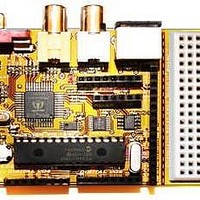
Chameleon-PIC
Manufacturer Part Number
Chameleon-PIC
Description
MCU, MPU & DSP Development Tools PIC24 & PROPELLER DEV SYSTEM (SBC)
Manufacturer
Nurve Networks
Datasheet
1.CHAMELEON-PIC.pdf
(263 pages)
Specifications of Chameleon-PIC
Processor To Be Evaluated
PIC24
Data Bus Width
16 bit
Interface Type
USB, VGA, PS/2, I2C, ISP, SPI
Operating Supply Voltage
3.3 V, 5 V
Lead Free Status / RoHS Status
Lead free / RoHS Compliant


Step 1: Wait for the keyboard to stop sending data (if you want to play nice). This means that both the DATA and CLOCK
lines will be in a HIGH state.
Step 2 (Initiate transmission): The host drives the CLOCK line LOW for 60us to tell the keyboard to stop all
transmissions. This is redundant if you waited for Step 1; however, the keyboard might not want to shut up, therefore, this
is how you force it to stop and listen.
Step 3 (Data ready for transmission): Drive the DATA line LOW, then release the CLOCK line (by release we mean not
to put a HIGH or a LOW, but to set the CLOCK into a tristate or input mode, so the keyboard can control it). This puts the
keyboard into the “receiver” state.
Step 4 (Write data): Now, the keyboard will generate a clock signal on the CLOCK line, you sample the DATA line when
the CLOCK line is HIGH and send it. The host program should serialize the command data (explained momentarily) made
up of 8-bits, a parity bit, and a stop bit for a total of 11-bits.
Step 5 (End transmission): Once the last data bit is sent then the parity (odd parity) and stop bit is sent then the host
drives the DATA line (Stop bit) and releases the DATA line.
12.1.4 Keyboard Commands
Table 12.4 illustrates some of the commands one can send to a generic keyboard based on the 8042 keyboard controller
originally in the IBM PC spec. This table is not exhaustive and only a reference, many keyboards don’t follow the
commands 100% and/or have other commands, so be weary of the commands.
Code
$ED
$EE
$F0
$F2
$F3
Description
Set/Reset Mode Indicators, keyboard responds with ACK then waits for a following option byte. When the option
byte is received the keyboard again ACK's and then sets the LED's accordingly. Scanning is resumed if scanning
was enabled. If another command is received instead of the option byte (high bit set on) this command is
terminated. Hardware defaults to these indicators turned off.
|7-3|2|1|0| Keyboard Status Indicator Option Byte
Diagnostic Echo, keyboard echoes the $EE byte back to the system without an acknowledgement.
PS/2 Select/Read Alternate Scan Code Sets, instructs keyboard to use one of the three make/break scan code
sets. Keyboard responds by clearing the output buffer/typematic key and then transmits an ACK. The system
must follow up by sending an option byte which will again be ACK'ed by the keyboard:
PS/2 Read Keyboard ID, keyboard responds with an ACK and a two byte keyboard ID of 83AB.
Set Typematic Rate/Delay, keyboard responds with ACK and waits for rate/delay byte. Upon receipt of the
rate/delay byte the keyboard responds with an ACK, then sets the new typematic values and scanning continues
if scanning was enabled.
Typematic Rate/Delay Option Byte
|7|6|5|4|3|2|1|0|
00 return byte indicating scan code set in use.
01 select scan code set 1 (used on PC & XT).
02 select scan code set 2.
03 select scan code set 3.
| | | |-+-+-+-+---- typematic rate indicator (see INT 16,3)
| | | | | `-------- A in period formula (see below)
| | | `------------ B is period formula (see below)
|
|
|
`---------- reserved
| | `--- Scroll-Lock indicator
| `----- Num-Lock indicator
`------- Caps-Lock indicator
Table 12.4 – Keyboard Commands.
(0=off, 1=on)
(0=off, 1=on)
(0=off, 1=on)
(must be zero)
© 2009 NURVE NETWORKS LLC “Exploring the Chameleon PIC 16-Bit”
60
Related parts for Chameleon-PIC
Image
Part Number
Description
Manufacturer
Datasheet
Request
R

Part Number:
Description:
MCU, MPU & DSP Development Tools AVR8 VIDEO GAME DEV SYSTEM (SBC)
Manufacturer:
Nurve Networks

Part Number:
Description:
MCU, MPU & DSP Development Tools PIC24 VIDEO GAME DEV SYSTEM (SBC)
Manufacturer:
Nurve Networks

Part Number:
Description:
MCU, MPU & DSP Development Tools AVR8 & PROPELLER DEV SYSTEM (SBC)
Manufacturer:
Nurve Networks
Datasheet: