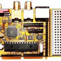
Chameleon-PIC Nurve Networks, Chameleon-PIC Datasheet - Page 31

Chameleon-PIC
Manufacturer Part Number
Chameleon-PIC
Description
MCU, MPU & DSP Development Tools PIC24 & PROPELLER DEV SYSTEM (SBC)
Manufacturer
Nurve Networks
Datasheet
1.CHAMELEON-PIC.pdf
(263 pages)
Specifications of Chameleon-PIC
Processor To Be Evaluated
PIC24
Data Bus Width
16 bit
Interface Type
USB, VGA, PS/2, I2C, ISP, SPI
Operating Supply Voltage
3.3 V, 5 V
Lead Free Status / RoHS Status
Lead free / RoHS Compliant
- Current page: 31 of 263
- Download datasheet (12Mb)
© 2009 NURVE NETWORKS LLC “Exploring the Chameleon PIC 16-Bit”
2.0 5.0V & 3.3V Power Supplies
Figure 2.1 – The Chameleon PIC power supply design.
The Chameleon PIC system has a duel 3.3V / 5.0V power supply system that is feed by a single 9V DC unregulated input
from a wall adapter or feeds from the USB port header. The supplies design is shown in Figure 2.1 for reference. The
supplies are straight forward, the only interesting thing is the coupling of the USB power and the regulated power at node
1 of the power switch SW1. This allows the system to use power from either the regulated supply or the USB port. The
Chameleon PIC is a mixed voltage system to support 5V I/O and 3.3V PIC and Propeller chips. Both supplies are
independent and can each supply up to 500 mA for all your needs. Additionally, the power supplies are exported to the
expansion header J7 for external interfacing.
3.0 Reset Circuit
Figure 3.1 – The Chameleon PIC reset circuit.
The Chameleon PIC can be reset externally via a number of sources including the reset switch SW2, the ISP
programming port as well as pressing as thru the DTR or RTS lines of the USB UART. The reset circuitry on the PIC 328P
31
Related parts for Chameleon-PIC
Image
Part Number
Description
Manufacturer
Datasheet
Request
R

Part Number:
Description:
MCU, MPU & DSP Development Tools AVR8 VIDEO GAME DEV SYSTEM (SBC)
Manufacturer:
Nurve Networks

Part Number:
Description:
MCU, MPU & DSP Development Tools PIC24 VIDEO GAME DEV SYSTEM (SBC)
Manufacturer:
Nurve Networks

Part Number:
Description:
MCU, MPU & DSP Development Tools AVR8 & PROPELLER DEV SYSTEM (SBC)
Manufacturer:
Nurve Networks
Datasheet:


