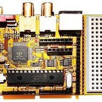
Chameleon-PIC Nurve Networks, Chameleon-PIC Datasheet - Page 58

Chameleon-PIC
Manufacturer Part Number
Chameleon-PIC
Description
MCU, MPU & DSP Development Tools PIC24 & PROPELLER DEV SYSTEM (SBC)
Manufacturer
Nurve Networks
Datasheet
1.CHAMELEON-PIC.pdf
(263 pages)
Specifications of Chameleon-PIC
Processor To Be Evaluated
PIC24
Data Bus Width
16 bit
Interface Type
USB, VGA, PS/2, I2C, ISP, SPI
Operating Supply Voltage
3.3 V, 5 V
Lead Free Status / RoHS Status
Lead free / RoHS Compliant
- Current page: 58 of 263
- Download datasheet (12Mb)
The keyboard hardware interface is either an old style male 5-pin DIN or a new PS/2 male 6-pin mini-DIN connector. The
6-pin mini DIN’s pin out is shown in Figure 12.2 (referenced looking at the computer’s female side where you plug the
keyboard into, notice the staggering of the pin numbering).
Table 12.3 lists the signals for reference, the descriptions of the signals are as follows:
DATA
CLOCK
VCC/GND
When both the keyboard and the host are inactive the CLOCK and DATA lines should be HIGH (inactive).
12.1.1 Communication Protocol from Keyboard to Host
When a key is pressed on the keyboard, the keyboard logic sends the make scan code to the host computer. The scan
code data it is clocked out by the keyboard in an 11-bit packet, the packet is shown in Figure 12.3. The packet consists of
0
1
2
3
4
5
6
7
8
45
16
1E
26
25
2E
36
3D
3E
Bi-directional and used to send and receive data.
Bi-directional; however, the keyboard nearly always controls it. The host can pull the CLOCK line LOW
though to inhibit transmissions, additionally during host -> keyboard communications the CLOCK line is
used as a request to send line of sorts to initiate the host -> keyboard transmission. This is used when
commands or setting need to be sent to the keyboard.
Power for the keyboard (or mouse). Specifications state no more than 100mA will be drawn, but I
wouldn’t count on it and plan for 200mA for feature rich keyboards with lots of lights etc.
F0,45
F0,16
F0,1E
F0,26
F0,25
F0,2E
F0,36
F0,3D
F0,3E
Figure 12.2 - Female PS/2 6-Pin Mini Din Connector at Chameleon PIC socket.
SCROLL
PAUSE
PRNT
SCRN
F10
F11
F12
F7
F8
F9
Table 12.3 – Pin out of PS/2 6-Pin Mini Din.
Pin
1
2
3
4
5
6
E1,14,77,
E1,F0,14,
Function
DATA (bi-directional open collector).
NC.
GROUND.
VCC (+5 @ 100 mA).
CLOCK.
NC.
E0,12,
E0,7C
F0,77
83
0A
01
09
78
07
7E
-NONE-
© 2009 NURVE NETWORKS LLC “Exploring the Chameleon PIC 16-Bit”
E0,F0,
7C,E0,
F0,12
F0,83
F0,0A
F0,01
F0,09
F0,78
F0,07
F0,7E
KP 8
KP 9
]
;
'
,
.
/
75
7D
5B
4C
52
41
49
4A
F0,75
F0,7D
F0,5B
F0,4C
F0,52
F0,41
F0,49
F0,4A
58
Related parts for Chameleon-PIC
Image
Part Number
Description
Manufacturer
Datasheet
Request
R

Part Number:
Description:
MCU, MPU & DSP Development Tools AVR8 VIDEO GAME DEV SYSTEM (SBC)
Manufacturer:
Nurve Networks

Part Number:
Description:
MCU, MPU & DSP Development Tools PIC24 VIDEO GAME DEV SYSTEM (SBC)
Manufacturer:
Nurve Networks

Part Number:
Description:
MCU, MPU & DSP Development Tools AVR8 & PROPELLER DEV SYSTEM (SBC)
Manufacturer:
Nurve Networks
Datasheet:


