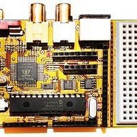
Chameleon-PIC Nurve Networks, Chameleon-PIC Datasheet - Page 70

Chameleon-PIC
Manufacturer Part Number
Chameleon-PIC
Description
MCU, MPU & DSP Development Tools PIC24 & PROPELLER DEV SYSTEM (SBC)
Manufacturer
Nurve Networks
Datasheet
1.CHAMELEON-PIC.pdf
(263 pages)
Specifications of Chameleon-PIC
Processor To Be Evaluated
PIC24
Data Bus Width
16 bit
Interface Type
USB, VGA, PS/2, I2C, ISP, SPI
Operating Supply Voltage
3.3 V, 5 V
Lead Free Status / RoHS Status
Lead free / RoHS Compliant
- Current page: 70 of 263
- Download datasheet (12Mb)
14.1 A Little Background on Low Pass Filters (EE stuff)
The signal Vin(t) comes in at the port and the low pass filter made up of R14 and C15 pass low frequencies, but block
high frequencies. This is what’s called a “single pole RC filter”. The “gain” of the filter or the “transfer function”
describes the relationship between the output and the input signal, thus a signal with a gain of 1 at the output, call it
Vout(t) would be equal to the input (with some possible phase variance, but this is irrelevant for our discussion). The
single pole RC filter acts like a voltage divider, but we have to use more complex math to describe it based on imaginary
numbers and/or differential equations. This is a tough, but there is a trick based on the Laplace Transform which
transforms differential equations into algebraic equations (called the S-Domain) then we can work with the circuit as if it
were made of resistors then transform back when done. This is all not that important, but it’s fun to know a little about
analog stuff, so let’s continue.
So given all that, we want to know what the voltage or signal is at the top of C15 (Vout) since this signal or voltage will
then affect the remainder of the circuit. Using a voltage divider made of R14 and C15, we need to write a relationship
between the input voltage at AUDIO_MONO, call it Vin(t) and the output voltage of the RC filter at the top of C15, call it
Vout(t). Ok, here goes a few steps:
Then dividing both sides by Vin(s) we get,
Simplifying a bit, results in,
Then transforming back from the S-domain to the frequency domain we get,
Note: Technically there is another term in there relating to phase, but it’s not important for this discussion. In any event,
now this is interesting, this equation:
Describes the amplification or more correctly the attenuation of our signal as a function of frequency f. This is very
interesting. Let’s try something fun. Let’s plug in some values really quickly and see what happens, let’s try 0 Hz, 1 Hz,
100 Hz, 1000 Hz, 1 MHz and see what we get. Table 14.1 shows the results.
This is very interesting, ignoring for a moment the actually values of RC, we see that very quickly larger values of f
(frequency) very quickly dominate the denominator and the quotient goes to 0. This is why this filter is called a “single
pole”, as the term in the denominator goes to infinity the quotient goes to zero. Ok, so how does this help us? Well, if we
select values of RC, we can tune the frequency that this “attenuation” gets really strong. This is typically called the 3dB
point, that is the point where the signal is attenuated by 3dB (decibels), not really important, to know what a decibels is,
it’s a measure of power or ratio of signals more or less, but what is important is that 3dB is about 70% of the signal, so if
you want to filter out everything above 10KHz you would set the 3dB point for about 10KHz (maybe a bit more) and you
would see the signal get filtered. Also, note that at DC, frequency f=0, the right hand term in the denominator sum (1 +
2*PI*0*RC) = 1, thus the gain is 1/1 or 1.0 which is exactly what it should be! Cool huh!
Vout(s) = Vin(s) * [ (1/sC) / (R + 1/sC)]
Gain = H(s) = [ (1/sC) / (R + 1/sC)]
Gain = H(s) = 1 / (1+sRC)
Gain = H(f) = 1 / (1 + 2*PI*f*RC)
Gain = H(f) = 1 / (1 + 2*PI*f*RC)
Table 14.1 – The results of passing various frequencies thru a low pass single pole RC filter.
Frequency f Hz
0
1
10
100
1000
1,000,000
Gain
1/1
1/(1+2*PI*RC)
1/(1+2*PI*10*RC)
1/(1+2*PI*100*RC)
1/(1+2*PI*1000*RC)
1/(1+2*PI*1,000,000*RC)
© 2009 NURVE NETWORKS LLC “Exploring the Chameleon PIC 16-Bit”
Comments
DC gain is 1.0 or no attenuation
70
Related parts for Chameleon-PIC
Image
Part Number
Description
Manufacturer
Datasheet
Request
R

Part Number:
Description:
MCU, MPU & DSP Development Tools AVR8 VIDEO GAME DEV SYSTEM (SBC)
Manufacturer:
Nurve Networks

Part Number:
Description:
MCU, MPU & DSP Development Tools PIC24 VIDEO GAME DEV SYSTEM (SBC)
Manufacturer:
Nurve Networks

Part Number:
Description:
MCU, MPU & DSP Development Tools AVR8 & PROPELLER DEV SYSTEM (SBC)
Manufacturer:
Nurve Networks
Datasheet:


