SPEAR320-2 STMicroelectronics, SPEAR320-2 Datasheet - Page 23

SPEAR320-2
Manufacturer Part Number
SPEAR320-2
Description
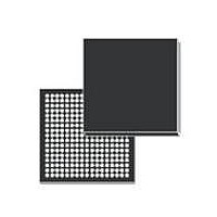
IC MPU ARM9 289LFBGA
Manufacturer
STMicroelectronics
Series
SPEAr®r
Datasheet
1.SPEAR320-2.pdf
(76 pages)
Specifications of SPEAR320-2
Processor Type
ARM Microprocessor
Speed
333MHz
Voltage
1.14 V ~ 3.6 V
Mounting Type
Surface Mount
Package / Case
289-LFBGA
Processor Series
SPEAr320
Core
ARM926EJ-S
Data Bus Width
16 bit
Maximum Clock Frequency
333 MHz
Operating Supply Voltage
1.2 V
Maximum Operating Temperature
+ 85 C
Mounting Style
SMD/SMT
Data Ram Size
8 KB
Interface Type
I2C, UART, USB, Serial
Number Of Programmable I/os
102
Number Of Timers
4
Program Memory Size
32 KB
Program Memory Type
ROM
Lead Free Status / RoHS Status
Lead free / RoHS Compliant
Features
-
Lead Free Status / Rohs Status
Lead free / RoHS Compliant
Other names
497-10843
Available stocks
Company
Part Number
Manufacturer
Quantity
Price
SPEAr320
3.23.2
3.24
3.25
Clock and reset system
The clock system is a fully programmable block that generates all the clocks necessary to
the chip.
The default operating clock frequencies are:
●
●
●
●
The default values give the maximum allowed clock frequencies. The clock frequencies are
fully programmable through dedicated registers.
The clock system consists of 2 main parts: a multi clock generator block and two internal
PLLs.
The multi clock generator block, takes a reference signal (which is usually delivered by the
PLL), generates all clocks for the IPs of SPEAr320 according to dedicated programmable
registers.
Each PLL uses an oscillator input of 24 MHz to generate a clock signal at a frequency
corresponding at the highest of the group. This is the reference signal used by the multi
clock generator block to obtain all the other requested clocks for the group. Its main feature
is electromagnetic interference reduction capability.
The user can set up the PLL in order to modulate the VCO with a triangular wave. The
resulting signal has a spectrum (and power) spread over a small programmable range of
frequencies centered on F0 (the VCO frequency), obtaining minimum electromagnetic
emissions. This method replaces all the other traditional methods of EMI reduction, such as
filtering, ferrite beads, chokes, adding power layers and ground planes to PCBs, metal
shielding and so on. This gives the customer appreciable cost savings.
In sleep mode the SPEAr320 runs with the PLL disabled so the available frequency is 24
MHz or a sub-multiple (/2, /4, /8).
Vectored interrupt controller (VIC)
The VIC allows the OS interrupt handler to quickly dispatch interrupt service routines in
response to peripheral interrupts. There are 32 interrupt lines and the VIC uses a separate
bit position for each interrupt source. Software controls each request line to generate
software interrupts.
General purpose timers
SPEAr320 provides 6 general purpose timers (GPTs) acting as APB slaves.
Each GPT consists of 2 channels, each one made up of a programmable 16-bit counter and
a dedicated 8-bit timer clock prescaler. The programmable 8-bit prescaler performs a clock
division by 1 up to 256, and different input frequencies can be chosen through configuration
registers (a frequency range from 3.96 Hz to 48 MHz can be synthesized).
Clock @ 333 MHz for the CPU.
Clock @ 166 MHz for AHB bus and AHB peripherals.
Clock @ 83 MHz for, APB bus and APB peripherals.
Clock @ 333 MHz for DDR memory interface.
Doc ID 16755 Rev 4
Architecture overview
23/76


