DR-TRC104-2400-DK RFM, DR-TRC104-2400-DK Datasheet - Page 6
DR-TRC104-2400-DK
Manufacturer Part Number
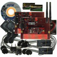
DR-TRC104-2400-DK
Description
KIT DEV FOR TRC104
Manufacturer
RFM
Type
Transceiverr
Datasheets
1.DR-TRC104-2400-DK.pdf
(33 pages)
2.DR-TRC104-2400-DK.pdf
(1 pages)
3.DR-TRC104-2400-DK.pdf
(2 pages)
Specifications of DR-TRC104-2400-DK
Frequency
2.4GHz
For Use With/related Products
TRC104
Lead Free Status / RoHS Status
Lead free / RoHS Compliant
Other names
583-1137


2.2 AC Electrical Characteristics
Minimum/maximum values are valid over the recommended operating range Vcc = 1.9-3.6 V. Typical conditions: T
The electrical specifications given below are valid when using an RFM XTL1021 or equivalent crystal.
www.RFM.com
©2009 by RF Monolithics, Inc.
PARAMETER
RF Input Impedance
RF Input Power
Receiver Bandwidth
Receiver Sensitivity
Blocking Immunity
Co-channel Rejection
Image Rejection
FSK Bit Rate
RSSI Accuracy
RSSI Dynamic Range
PARAMETER
RF Output Impedance
RF Output Power
RF Output Power Range
2
3
2
3
FSK Deviation
20 dB Modulation BW
nd
rd
nd
rd
Adjacent Channel Power
Harmonic
Adjacent Channel Power
Harmonic
E-mail:
info@rfm.com
SYM
SYM
2 MHz channel offset
3 MHz channel offset
Technical support +1.800.704.6079
4-bit value
250 kb/s
250 kb/s
250 kb/s
250 kb/s
NOTES
NOTES
1 Mb/s
1 Mb/s
1 Mb/s
1 Mb/s
TRANSMITTER
RECEIVER
Table 5
Table 6
MIN
MIN
250
-20
±160
TYP
TYP
200
200
1.5
-95
-90
-20
-26
-26
-20
-40
-54
-46
±3
40
9
5
1
0
1
MAX
1000
MAX
0
0
UNITS
UNITS
ohms
ohms
dBm
MHz
dBm
dBm
dBm
dBm
dBm
dBm
dBm
MHz
kb/s
kHz
dB
dB
dB
dB
dB
O
= 25°C; V
TRC104 - 08/13/09
Test Conditions
1 Mb/s data rate,
0 dBm TX power
1 Mb/s data rate,
0 dBm TX power
0 dBm TX power
0 dBm TX power
Test Condition
programmable
1 MHz offset,
unmodulated
fixed for both
CC
differential
differential
data rates
10
10
= 3.3 V.
Page 6 of 33
NRZ
-3
-3
BER
BER
Related parts for DR-TRC104-2400-DK
Image
Part Number
Description
Manufacturer
Datasheet
Request
R

Part Number:
Description:
ASH RX 115.2 KBPS 433.92 MHZ
Manufacturer:
RFM
Datasheet:

Part Number:
Description:
RFIC TRANCEIVER MULTI-CHANNEL FS
Manufacturer:
RFM
Datasheet:

Part Number:
Description:
ASH TX 115.2 KBPS 433.92 MHZ
Manufacturer:
RFM
Datasheet:
Part Number:
Description:
Filters 1602MHz BW=61MHz
Manufacturer:
RFM
Datasheet:

Part Number:
Description:
RESONATOR, SM3030-6
Manufacturer:
RFM
Datasheet:

Part Number:
Description:
RESONATOR, SM3030-6
Manufacturer:
RFM
Datasheet:

Part Number:
Description:
RESONATOR, SM3030-6
Manufacturer:
RFM
Datasheet:

Part Number:
Description:
RESONATOR, SM5035-4
Manufacturer:
RFM
Datasheet:
Part Number:
Description:
RESONATOR 418MHZ SM5035-4
Manufacturer:
RFM
Datasheet:
Part Number:
Description:
RESONATOR 315 MHZ SMD
Manufacturer:
RFM
Datasheet:
Part Number:
Description:
WiFi / 802.11 Modules 2.4 and 5.8GHz + BT
Manufacturer:
RFM
Datasheet:

Part Number:
Description:
10-Terminal Ceramic Surface-Mount Case 7 x 5 mm Nominal Footprint
Manufacturer:
RFM [RF Monolithics, Inc]
Datasheet:
Part Number:
Description:
QUAD-BAND GSM850/GSM/DCS/PCS POWER AMP MODULE
Manufacturer:
RFM [RF Monolithics, Inc]
Datasheet:
Part Number:
Description:
402 to 405 MHz Medical Band Front-end Filter
Manufacturer:
RFM [RF Monolithics, Inc]
Datasheet: