DR-TRC104-2400-DK RFM, DR-TRC104-2400-DK Datasheet - Page 15
DR-TRC104-2400-DK
Manufacturer Part Number
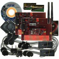
DR-TRC104-2400-DK
Description
KIT DEV FOR TRC104
Manufacturer
RFM
Type
Transceiverr
Datasheets
1.DR-TRC104-2400-DK.pdf
(33 pages)
2.DR-TRC104-2400-DK.pdf
(1 pages)
3.DR-TRC104-2400-DK.pdf
(2 pages)
Specifications of DR-TRC104-2400-DK
Frequency
2.4GHz
For Use With/related Products
TRC104
Lead Free Status / RoHS Status
Lead free / RoHS Compliant
Other names
583-1137


address detection are disabled. The TRC104 host microcontroller must handle functions such as DC-balanced
data scrambling and CRC generation for Continuous Receive Mode. Note that a valid sender (local device)
address is required for address detection and proper Continuous Receive Mode operation. This address is
configured by writing the address byte(s) into configuration registers 0x0E - 0x12, according to the address length
specified by the ADDR_len bits in configuration register 0x08. The sender address is written least significant byte
first, starting in register 0x0E.
The host microcontroller must be powerful enough to handle the chosen serial data rate (250 kb/s or 1 Mb/s) in
addition to the other functions required for the end application. Data is read from the SDAT pin. To assist in data
recovery, a bit clock is available on the SCLK pin. The state of the SDAT pin is read on the rising edge of SCLK to
recover the demodulated data. Figure 12 and Table 11 show the timing for reading data from SDAT.
5.2 Burst Packet Modes
Burst Packet Mode is enabled when the D_Mode bit of register 0x02 is set to 1. Burst Packet Mode handles
automatic packet features such as preamble generation, address insertion and filtering, DC-balanced data
scrambling/descrambling, and CRC generation and error detection. In Burst Packet Mode the FIFO is enabled
and used for transmitting or receiving packets. In Burst Packet Mode, the host microcontroller does not have the
heavy overhead of bit, byte and packet processing as is the case with the Continuous Mode.
5.2.1 Burst Transmit Mode
Burst Transmit Mode is enabled when the C_Mode bit of configuration register 0x00 is set to 1 and the D_Mode
bit of register 0x02 is set to 1. In Burst Transmit Mode, data is written to the TRC104 before being transmitted,
most significant bit or each byte first. The automatic packet features listed in Section 5.2 are available in Burst
Mode. Once the FIFO is loaded, three additional dummy bits (any value) are clocked in. The MODE pin is then
de-asserted (low) and the packet transmission starts. At the end of the transmission the INT flag is asserted. The
INT flag resets when the TRC104 is placed in another mode. Figure 13 and Table 12 show the serial port timing
parameters for Burst Transmit Mode.
In Burst Mode, the FIFO length is set to match the number of payload data bytes. When transmitting a packet ,
the destination address may obtained from one of two sources, either automatically from configuration registers
www.RFM.com
©2009 by RF Monolithics, Inc.
E-mail:
info@rfm.com
Item
T1
T2
T3
MODE to SCLK Time
Bit Delay Time
Description
SCLK Cycle Time for 1 Mb/s
SCLK Cycle Time for 250 kb/s
Technical support +1.800.704.6079
Figure 12
Table 11
Min
Typ
250
15
1
4
Max
Unit
µs
µs
ns
TRC104 - 08/13/09
Page 15 of 33
Related parts for DR-TRC104-2400-DK
Image
Part Number
Description
Manufacturer
Datasheet
Request
R

Part Number:
Description:
ASH RX 115.2 KBPS 433.92 MHZ
Manufacturer:
RFM
Datasheet:

Part Number:
Description:
RFIC TRANCEIVER MULTI-CHANNEL FS
Manufacturer:
RFM
Datasheet:

Part Number:
Description:
ASH TX 115.2 KBPS 433.92 MHZ
Manufacturer:
RFM
Datasheet:
Part Number:
Description:
Filters 1602MHz BW=61MHz
Manufacturer:
RFM
Datasheet:

Part Number:
Description:
RESONATOR, SM3030-6
Manufacturer:
RFM
Datasheet:

Part Number:
Description:
RESONATOR, SM3030-6
Manufacturer:
RFM
Datasheet:

Part Number:
Description:
RESONATOR, SM3030-6
Manufacturer:
RFM
Datasheet:

Part Number:
Description:
RESONATOR, SM5035-4
Manufacturer:
RFM
Datasheet:
Part Number:
Description:
RESONATOR 418MHZ SM5035-4
Manufacturer:
RFM
Datasheet:
Part Number:
Description:
RESONATOR 315 MHZ SMD
Manufacturer:
RFM
Datasheet:
Part Number:
Description:
WiFi / 802.11 Modules 2.4 and 5.8GHz + BT
Manufacturer:
RFM
Datasheet:

Part Number:
Description:
10-Terminal Ceramic Surface-Mount Case 7 x 5 mm Nominal Footprint
Manufacturer:
RFM [RF Monolithics, Inc]
Datasheet:
Part Number:
Description:
QUAD-BAND GSM850/GSM/DCS/PCS POWER AMP MODULE
Manufacturer:
RFM [RF Monolithics, Inc]
Datasheet:
Part Number:
Description:
402 to 405 MHz Medical Band Front-end Filter
Manufacturer:
RFM [RF Monolithics, Inc]
Datasheet: