DR-TRC104-2400-DK RFM, DR-TRC104-2400-DK Datasheet - Page 5
DR-TRC104-2400-DK
Manufacturer Part Number
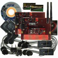
DR-TRC104-2400-DK
Description
KIT DEV FOR TRC104
Manufacturer
RFM
Type
Transceiverr
Datasheets
1.DR-TRC104-2400-DK.pdf
(33 pages)
2.DR-TRC104-2400-DK.pdf
(1 pages)
3.DR-TRC104-2400-DK.pdf
(2 pages)
Specifications of DR-TRC104-2400-DK
Frequency
2.4GHz
For Use With/related Products
TRC104
Lead Free Status / RoHS Status
Lead free / RoHS Compliant
Other names
583-1137


2 Electrical Characteristics
Absolute Maximum Ratings
Recommended Operating Range
2.1 DC Electrical Characteristics
Minimum/maximum values are valid over the recommended operating range Vcc = 1.9-3.6 V. Typical conditions: T
The electrical specifications given below are valid when using an RFM XTL1021 or equivalent crystal.
www.RFM.com
©2009 by RF Monolithics, Inc.
SYMBOL
Vcc
T
RF
SYMBOL
Vcc
T
PARAMETER
Sleep Mode Current
Stop Mode Current
Standby Mode Current
Configuration Mode Current
Receiver Mode Current
Transmitter Mode Current
RSSI Analog Output Level
Digital Input Low Level
Digital Input High Level
Digital Input Current Low
Digital Input Current High
Digital Output Low Level
Digital Output High Level
STG
OP
IN
PARAMETER
Supply Voltage
Operating Temperature
E-mail:
PARAMETER
Supply Voltage
Storage Temperature
RF Input Level
info@rfm.com
SYM
V
V
I
V
I
I
I
I
V
I
I
I
CM
ST
SB
RX
SL
TX
IH
OH
IL
OL
IH
IL
crystal oscillator running
crystal oscillator running
Pout = -10 dBm
Pout = 0 dBm
Technical support +1.800.704.6079
250 kb/s
NOTES
1 Mb/s
Table 2
Table 3
Table 4
NOTES
NOTES
Vcc-0.4
0.7*Vcc
MIN
-0.4
500
-
TYP
0.4
1.4
22
15
18
19
13
9
1
1
+1.9
MIN
MIN
-0.4
-55
-40
Vcc+0.4
MAX
1500
0.8
0.4
-
MAX
MAX
+125
+3.6
+3.6
+85
0
UNITS
mA
mA
mA
mV
µA
µA
µA
µA
µA
O
V
V
V
V
= 25°C; V
UNITS
UNITS
dBm
°C
°C
V
V
TRC104 - 08/13/09
Test Conditions
16 MHz crystal
I
CC
I
OH
OL
V
V
= 3.3 V.
IH
IL
= +1 mA
Page 5 of 33
= -1 mA
= Vcc
= 0 V
Related parts for DR-TRC104-2400-DK
Image
Part Number
Description
Manufacturer
Datasheet
Request
R

Part Number:
Description:
ASH RX 115.2 KBPS 433.92 MHZ
Manufacturer:
RFM
Datasheet:

Part Number:
Description:
RFIC TRANCEIVER MULTI-CHANNEL FS
Manufacturer:
RFM
Datasheet:

Part Number:
Description:
ASH TX 115.2 KBPS 433.92 MHZ
Manufacturer:
RFM
Datasheet:
Part Number:
Description:
Filters 1602MHz BW=61MHz
Manufacturer:
RFM
Datasheet:

Part Number:
Description:
RESONATOR, SM3030-6
Manufacturer:
RFM
Datasheet:

Part Number:
Description:
RESONATOR, SM3030-6
Manufacturer:
RFM
Datasheet:

Part Number:
Description:
RESONATOR, SM3030-6
Manufacturer:
RFM
Datasheet:

Part Number:
Description:
RESONATOR, SM5035-4
Manufacturer:
RFM
Datasheet:
Part Number:
Description:
RESONATOR 418MHZ SM5035-4
Manufacturer:
RFM
Datasheet:
Part Number:
Description:
RESONATOR 315 MHZ SMD
Manufacturer:
RFM
Datasheet:
Part Number:
Description:
WiFi / 802.11 Modules 2.4 and 5.8GHz + BT
Manufacturer:
RFM
Datasheet:

Part Number:
Description:
10-Terminal Ceramic Surface-Mount Case 7 x 5 mm Nominal Footprint
Manufacturer:
RFM [RF Monolithics, Inc]
Datasheet:
Part Number:
Description:
QUAD-BAND GSM850/GSM/DCS/PCS POWER AMP MODULE
Manufacturer:
RFM [RF Monolithics, Inc]
Datasheet:
Part Number:
Description:
402 to 405 MHz Medical Band Front-end Filter
Manufacturer:
RFM [RF Monolithics, Inc]
Datasheet: