DR-TRC104-2400-DK RFM, DR-TRC104-2400-DK Datasheet - Page 30
DR-TRC104-2400-DK
Manufacturer Part Number
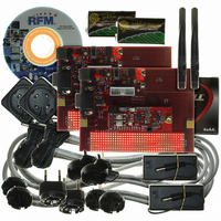
DR-TRC104-2400-DK
Description
KIT DEV FOR TRC104
Manufacturer
RFM
Type
Transceiverr
Datasheets
1.DR-TRC104-2400-DK.pdf
(33 pages)
2.DR-TRC104-2400-DK.pdf
(1 pages)
3.DR-TRC104-2400-DK.pdf
(2 pages)
Specifications of DR-TRC104-2400-DK
Frequency
2.4GHz
For Use With/related Products
TRC104
Lead Free Status / RoHS Status
Lead free / RoHS Compliant
Other names
583-1137


To support the specified configuration, 14 of the configuration register default values must be initialized to new
values. Only two calculations are required to determine the configuration register constants. The first calculation
is determining the value of Ch_Num in control register 0X00. The calculation is simple:
The second calculation determines the best PLL pre-start delay time. Ideally the PLL turn-on delay time as shown
in Figure 5 plus the 170 µs PLL lock time should equal the Burst Transmit Mode FIFO write time. Referring to
Figure 13 and Table 12, the FIFO write time for a 1 Mb/s serial clock rate is:
Given the short FIFO length and the 1 Mb/s serial write rate, the FIFO write time is shorter than the PLL lock time,
so no delay is necessary. A minimum delay of 20 µs must be set in the PLL Turn-on Control register to enable
PLL Pre-start function. Using the 20 µs delay value provides a net Pre-start time of:
If the FIFO was larger and/or the serial rate slower, the PLL Pre-start function would provide a bigger benefit.
www.RFM.com
©2009 by RF Monolithics, Inc.
1. To initialize each TRC104, enter Sleep Mode by setting control line PMODE to 0 and control line
2. Enter Configuration Mode by setting control line MODE to 0, and control lines CS and PMODE to 1.
3. Following the 120 ms reset period and holding the control lines in Configuration Mode, write the Ch_8_RX
4. For the base TRC104, write the following additional configuration constants to the radio, cycling the CS
F
Ch_Num = F
for 2408 MHz channel operation:
Ch_Num = 2408 - 2400 = 8
20 µs MODE to FIFO write
32 µs to write 4 bytes
55 µs total
55 - 20 = 35 µs, shorting the transmit turn on latency from to 170 - 35 = 135 µs
MODE to 1. Hold this state for 100 ms.
Hold for 120 ms to allow the radio to reset, which loads the power-on default values in all configuration
registers.
configuration constant 0X8008 to the TRC104 (base or remote). Set the CS control line to 0 for at least
5 µs, and then set the CS control line back to 1.
control line to 0 for at least 5 µs between each write:
3 µs to write the final three dummy bits
RF
TX_Pwr → 0X811B
FIFO_Sz → 0X8503
Pre_Ctl → 0X86B0
Addr_len → 0X8802
Bs_Snd_Lo → 0X8E01
Bs_Snd_Hi → 0X8FAA
Bs_Dst_Lo → 0X8902
Bs_Dst_Hi → 0X8AAA
PLL_Del → 0X9401
Ovr_2C → 0XAC18
= 2400 + Ch_Num, 1 ≤ Ch_Num ≤ 127, in MHz
or
E-mail:
RF
info@rfm.com
- 2400
Technical support +1.800.704.6079
TRC104 - 08/13/09
Page 30 of 33
Related parts for DR-TRC104-2400-DK
Image
Part Number
Description
Manufacturer
Datasheet
Request
R

Part Number:
Description:
ASH RX 115.2 KBPS 433.92 MHZ
Manufacturer:
RFM
Datasheet:

Part Number:
Description:
RFIC TRANCEIVER MULTI-CHANNEL FS
Manufacturer:
RFM
Datasheet:

Part Number:
Description:
ASH TX 115.2 KBPS 433.92 MHZ
Manufacturer:
RFM
Datasheet:
Part Number:
Description:
Filters 1602MHz BW=61MHz
Manufacturer:
RFM
Datasheet:

Part Number:
Description:
RESONATOR, SM3030-6
Manufacturer:
RFM
Datasheet:

Part Number:
Description:
RESONATOR, SM3030-6
Manufacturer:
RFM
Datasheet:

Part Number:
Description:
RESONATOR, SM3030-6
Manufacturer:
RFM
Datasheet:

Part Number:
Description:
RESONATOR, SM5035-4
Manufacturer:
RFM
Datasheet:
Part Number:
Description:
RESONATOR 418MHZ SM5035-4
Manufacturer:
RFM
Datasheet:
Part Number:
Description:
RESONATOR 315 MHZ SMD
Manufacturer:
RFM
Datasheet:
Part Number:
Description:
WiFi / 802.11 Modules 2.4 and 5.8GHz + BT
Manufacturer:
RFM
Datasheet:

Part Number:
Description:
10-Terminal Ceramic Surface-Mount Case 7 x 5 mm Nominal Footprint
Manufacturer:
RFM [RF Monolithics, Inc]
Datasheet:
Part Number:
Description:
QUAD-BAND GSM850/GSM/DCS/PCS POWER AMP MODULE
Manufacturer:
RFM [RF Monolithics, Inc]
Datasheet:
Part Number:
Description:
402 to 405 MHz Medical Band Front-end Filter
Manufacturer:
RFM [RF Monolithics, Inc]
Datasheet: