DR-TRC104-2400-DK RFM, DR-TRC104-2400-DK Datasheet - Page 4
DR-TRC104-2400-DK
Manufacturer Part Number
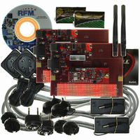
DR-TRC104-2400-DK
Description
KIT DEV FOR TRC104
Manufacturer
RFM
Type
Transceiverr
Datasheets
1.DR-TRC104-2400-DK.pdf
(33 pages)
2.DR-TRC104-2400-DK.pdf
(1 pages)
3.DR-TRC104-2400-DK.pdf
(2 pages)
Specifications of DR-TRC104-2400-DK
Frequency
2.4GHz
For Use With/related Products
TRC104
Lead Free Status / RoHS Status
Lead free / RoHS Compliant
Other names
583-1137


1 Pin Configuration
1.1 Pin Description
www.RFM.com
©2009 by RF Monolithics, Inc.
PIN
10
11
12
13
14
15
16
17
18
19
20
21
22
23
24
P
1
2
3
4
5
6
7
8
9
TYPE
RFIO
RFIO
E-mail:
I/O
I/O
O
O
O
O
I
I
I
I
-
info@rfm.com
NAME
GNDVCO
VCCVCO
DIE PAD
XTLOUT
PMODE
VDDRF
GNDRF
VCCRF
GNDIF
RSSID
MODE
GNDD
RSSIA
VCCD
VDDD
XTLIN
SCLK
SDAT
RF+
RF-
INT
NC
NC
NC
CS
DESCRIPTION
Operating mode select input - used with PMODE and CS
Serial clock input for burst mode, serial data output for continuous mode, and
SPI/FIFO clock signal
Serial data input/output for SPI mode and TX/RX active mode
SPI serial interface select, active high
External digital power input, 3.0 V typical
Digital ground
Regulated digital output voltage
Crystal oscillator output
Crystal oscillator input
Power mode select input - used with MODE to select standby or sleep mode
VCO ground pin
External VCO power input , 3.0 V typical
Regulated supply output for RF power amplifier
Differential RF I/O pin
Differential RF I/O pin
RF ground
External RF power input, 3.0 V typical
IF ground
Analog RSSI output - continuous mode only
No connection - not used
Transmit or receive complete interrupt output
RSSI threshold interrupt output
No connection - not used
No connection - not used
IC die pad on bottom of package - ground
Technical support +1.800.704.6079
Figure 1
Table 1
TRC104 - 08/13/09
Page 4 of 33
Related parts for DR-TRC104-2400-DK
Image
Part Number
Description
Manufacturer
Datasheet
Request
R

Part Number:
Description:
ASH RX 115.2 KBPS 433.92 MHZ
Manufacturer:
RFM
Datasheet:

Part Number:
Description:
RFIC TRANCEIVER MULTI-CHANNEL FS
Manufacturer:
RFM
Datasheet:

Part Number:
Description:
ASH TX 115.2 KBPS 433.92 MHZ
Manufacturer:
RFM
Datasheet:
Part Number:
Description:
Filters 1602MHz BW=61MHz
Manufacturer:
RFM
Datasheet:

Part Number:
Description:
RESONATOR, SM3030-6
Manufacturer:
RFM
Datasheet:

Part Number:
Description:
RESONATOR, SM3030-6
Manufacturer:
RFM
Datasheet:

Part Number:
Description:
RESONATOR, SM3030-6
Manufacturer:
RFM
Datasheet:

Part Number:
Description:
RESONATOR, SM5035-4
Manufacturer:
RFM
Datasheet:
Part Number:
Description:
RESONATOR 418MHZ SM5035-4
Manufacturer:
RFM
Datasheet:
Part Number:
Description:
RESONATOR 315 MHZ SMD
Manufacturer:
RFM
Datasheet:
Part Number:
Description:
WiFi / 802.11 Modules 2.4 and 5.8GHz + BT
Manufacturer:
RFM
Datasheet:

Part Number:
Description:
10-Terminal Ceramic Surface-Mount Case 7 x 5 mm Nominal Footprint
Manufacturer:
RFM [RF Monolithics, Inc]
Datasheet:
Part Number:
Description:
QUAD-BAND GSM850/GSM/DCS/PCS POWER AMP MODULE
Manufacturer:
RFM [RF Monolithics, Inc]
Datasheet:
Part Number:
Description:
402 to 405 MHz Medical Band Front-end Filter
Manufacturer:
RFM [RF Monolithics, Inc]
Datasheet: