DR-TRC104-2400-DK RFM, DR-TRC104-2400-DK Datasheet - Page 29
DR-TRC104-2400-DK
Manufacturer Part Number
DR-TRC104-2400-DK
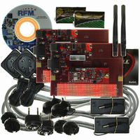
Description
KIT DEV FOR TRC104
Manufacturer
RFM
Type
Transceiverr
Datasheets
1.DR-TRC104-2400-DK.pdf
(33 pages)
2.DR-TRC104-2400-DK.pdf
(1 pages)
3.DR-TRC104-2400-DK.pdf
(2 pages)
Specifications of DR-TRC104-2400-DK
Frequency
2.4GHz
For Use With/related Products
TRC104
Lead Free Status / RoHS Status
Lead free / RoHS Compliant
Other names
583-1137


9 Configuration Example
This example details the configuration of a TRC104 application with the following specifications:
9.1 Burst Packet Mode Initialization
The following table of 16-bit register configuration constants are used to initialize and control the radios. The most
significant bit of the first byte is the configuration write bit. The next seven bits specify the register address. The
second byte specifies the register configuration.
www.RFM.com
©2009 by RF Monolithics, Inc.
Ch_8_RX
Ch_8_TX
TX_Pwr
FIFO_Sz
Pre_Ctl
Addr_Len
Bs_Snd_Lo
Bs_Snd_Hi
Bs_Dst_Lo
Bs_Dst_Hi
Rm_Snd_Lo
Rm_Snd_Hi
Rm_Dst_Lo
Rm_Dst_Hi
PLL_Del
Ovr_2C
Ovr_39
Ovr_4F
Ovr_77
Radios in System
Operating Frequency and Power
RF Data Rate
Address Length
Base Address
Remote Address
Destination Address
Sender Address Option
Sender Address Output on Receive
Payload Data Length
DC-Balanced Data Scrambling
CRC Error Detection
Packet Error Handling
PLL Pre-start
Power Amplifier Ramp Up/Down Timing
INT Flag Assertion State
Host Serial Clocking Rate
Label
E-mail:
info@rfm.com
Hex Constant
0X8AAA
0X8AAA
0X8FAA
0X8FAA
0XAC18
0XB9B9
0XCF66
0X8E01
0X8E02
0XF75C
0X8008
0X8088
0x811B
0X8503
0X8802
0X8902
0X8901
0X9401
0x86B0
T/R and Channel Control 0X00: RX, 2408 MHz
T/R and Channel Control 0X00: TX, 2408 MHz
TX Power and Crystal Frequency Control 0X01: 0 dBm, 16 MHz
Data Format Control 0x05: auto-insert destination in TX, auto-insert sender in TX, output
sender with RX, 4 byte FIFO
Preamble Control 0X06: default override for enhanced performance
Address Length Control 0X08: 2-byte addressing
Base Sender (Local Device) Low Address 0X0E: base low address byte
Base Sender (Local Device) High Address 0X0F: base high address byte
Base Destination Low Address 0X09: remote low address byte
Base Destination High Address 0X0A: remote high address byte
Remote Sender (Local Device) Low Address 0X0E: remote low address byte
Remote Sender (Local Device) High Address 0X0F: remote high address byte
Remote Destination Low Address 0X09: base low address byte
Remote Destination High Address 0X0A: base high address byte
PLL Turn-on Control Address 0X14: 20 µs delay
Register 0x2C: default override for enhanced performance
Register 0x39: default override for enhanced performance
Register 0x4F: default override for enhanced performance
Register 0x77: default override for enhanced performance
Technical support +1.800.704.6079
Base and remote
2408 MHz, 0 dBm
1 Mb/s
2 bytes
0XAA01
0XAA02
Auto-insert
Enabled, auto-insert
Enabled
4 bytes
Enabled
Enabled
Discard
Enabled
10/5 µs
High
1 Mb/s
Table 39
Configuration Register Detail
TRC104 - 08/13/09
Page 29 of 33
Related parts for DR-TRC104-2400-DK
Image
Part Number
Description
Manufacturer
Datasheet
Request
R

Part Number:
Description:
ASH RX 115.2 KBPS 433.92 MHZ
Manufacturer:
RFM
Datasheet:

Part Number:
Description:
RFIC TRANCEIVER MULTI-CHANNEL FS
Manufacturer:
RFM
Datasheet:

Part Number:
Description:
ASH TX 115.2 KBPS 433.92 MHZ
Manufacturer:
RFM
Datasheet:
Part Number:
Description:
Filters 1602MHz BW=61MHz
Manufacturer:
RFM
Datasheet:

Part Number:
Description:
RESONATOR, SM3030-6
Manufacturer:
RFM
Datasheet:

Part Number:
Description:
RESONATOR, SM3030-6
Manufacturer:
RFM
Datasheet:

Part Number:
Description:
RESONATOR, SM3030-6
Manufacturer:
RFM
Datasheet:

Part Number:
Description:
RESONATOR, SM5035-4
Manufacturer:
RFM
Datasheet:
Part Number:
Description:
RESONATOR 418MHZ SM5035-4
Manufacturer:
RFM
Datasheet:
Part Number:
Description:
RESONATOR 315 MHZ SMD
Manufacturer:
RFM
Datasheet:
Part Number:
Description:
WiFi / 802.11 Modules 2.4 and 5.8GHz + BT
Manufacturer:
RFM
Datasheet:

Part Number:
Description:
10-Terminal Ceramic Surface-Mount Case 7 x 5 mm Nominal Footprint
Manufacturer:
RFM [RF Monolithics, Inc]
Datasheet:
Part Number:
Description:
QUAD-BAND GSM850/GSM/DCS/PCS POWER AMP MODULE
Manufacturer:
RFM [RF Monolithics, Inc]
Datasheet:
Part Number:
Description:
402 to 405 MHz Medical Band Front-end Filter
Manufacturer:
RFM [RF Monolithics, Inc]
Datasheet: