DR-TRC104-2400-DK RFM, DR-TRC104-2400-DK Datasheet - Page 21
DR-TRC104-2400-DK
Manufacturer Part Number
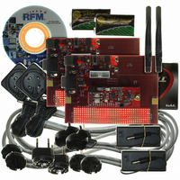
DR-TRC104-2400-DK
Description
KIT DEV FOR TRC104
Manufacturer
RFM
Type
Transceiverr
Datasheets
1.DR-TRC104-2400-DK.pdf
(33 pages)
2.DR-TRC104-2400-DK.pdf
(1 pages)
3.DR-TRC104-2400-DK.pdf
(2 pages)
Specifications of DR-TRC104-2400-DK
Frequency
2.4GHz
For Use With/related Products
TRC104
Lead Free Status / RoHS Status
Lead free / RoHS Compliant
Other names
583-1137


Figure 20 and Table 5 show the timing for a configuration write sequence to the TRC104.
7.2 Transmit/Receive FIFO Access
Serial data is sent or received through the FIFO according to the TRC104 mode of operation. If the TRC104 is
configured for Burst Receive Mode, a FIFO read transaction is implemented on the serial interface. If the TRC104
is configured for Burst Transmit Mode, a FIFO write transaction is implemented on the serial interface. The CS pin
must be held low during FIFO transactions. If the CS is allowed to go high, the TRC104 will interpret the data as a
register configuration transaction and possibly corrupt the device configuration. See Sections 5.2.1 and 5.2.2 for
details on Burst Transmit Mode and Burst Receive Mode using the FIFO.
8 Configuration Registers
The TRC104’s user configuration registers are mapped in the address range of 0x00 through 0x18. Sections 8.1
through 8.17 below provide the details for each configuration register. Power-up default settings for the
configuration register bit and byte patterns are shown in bold.
www.RFM.com
©2009 by RF Monolithics, Inc.
E-mail:
info@rfm.com
Item
T1
T2
T3
T4
T5
T6
Item
T1
T2
T3
T4
T5
Description
CS to 1
SCLK Cycle Time
Setup Time
Hold Time
Data Bit Hold Time
Last Bit to CS Time
Description
CS to 1
SCLK cycle time
Setup time
Hold time
Last bit to CS time
Technical support +1.800.704.6079
st
st
Bit Time
bit time
Figure 20
Table 14
Table 15
Min
200
Min
200
20
10
10
50
20
10
10
50
Typ
Typ
Max
Max
20
Unit
µs
ns
ns
ns
ns
Unit
µs
ns
ns
ns
ns
ns
TRC104 - 08/13/09
Page 21 of 33
Related parts for DR-TRC104-2400-DK
Image
Part Number
Description
Manufacturer
Datasheet
Request
R

Part Number:
Description:
ASH RX 115.2 KBPS 433.92 MHZ
Manufacturer:
RFM
Datasheet:

Part Number:
Description:
RFIC TRANCEIVER MULTI-CHANNEL FS
Manufacturer:
RFM
Datasheet:

Part Number:
Description:
ASH TX 115.2 KBPS 433.92 MHZ
Manufacturer:
RFM
Datasheet:
Part Number:
Description:
Filters 1602MHz BW=61MHz
Manufacturer:
RFM
Datasheet:

Part Number:
Description:
RESONATOR, SM3030-6
Manufacturer:
RFM
Datasheet:

Part Number:
Description:
RESONATOR, SM3030-6
Manufacturer:
RFM
Datasheet:

Part Number:
Description:
RESONATOR, SM3030-6
Manufacturer:
RFM
Datasheet:

Part Number:
Description:
RESONATOR, SM5035-4
Manufacturer:
RFM
Datasheet:
Part Number:
Description:
RESONATOR 418MHZ SM5035-4
Manufacturer:
RFM
Datasheet:
Part Number:
Description:
RESONATOR 315 MHZ SMD
Manufacturer:
RFM
Datasheet:
Part Number:
Description:
WiFi / 802.11 Modules 2.4 and 5.8GHz + BT
Manufacturer:
RFM
Datasheet:

Part Number:
Description:
10-Terminal Ceramic Surface-Mount Case 7 x 5 mm Nominal Footprint
Manufacturer:
RFM [RF Monolithics, Inc]
Datasheet:
Part Number:
Description:
QUAD-BAND GSM850/GSM/DCS/PCS POWER AMP MODULE
Manufacturer:
RFM [RF Monolithics, Inc]
Datasheet:
Part Number:
Description:
402 to 405 MHz Medical Band Front-end Filter
Manufacturer:
RFM [RF Monolithics, Inc]
Datasheet: