DR-TRC104-2400-DK RFM, DR-TRC104-2400-DK Datasheet - Page 18
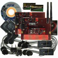
DR-TRC104-2400-DK
Manufacturer Part Number
DR-TRC104-2400-DK
Description
KIT DEV FOR TRC104
Manufacturer
RFM
Type
Transceiverr
Datasheets
1.DR-TRC104-2400-DK.pdf
(33 pages)
2.DR-TRC104-2400-DK.pdf
(1 pages)
3.DR-TRC104-2400-DK.pdf
(2 pages)
Specifications of DR-TRC104-2400-DK
Frequency
2.4GHz
For Use With/related Products
TRC104
Lead Free Status / RoHS Status
Lead free / RoHS Compliant
Other names
583-1137


6.1 FIFO Configuration
The transmit/receive FIFO length is set with the FIFO_len bits in configuration register 0X05. The length can be
set from one to 32 bytes. The FIFO must be long enough to hold all payload data bytes. All TRC104 radios in a
network must use the same FIFO length. The FIFO must be completely filled on every transmission. Padding
bytes (user selected value) are used to fill up the transmit FIFO when payload data bytes do not completely fill it.
6.2 Preamble Configuration
The preamble is a 1-0-1-0… sequence of bits sent at the beginning of a packet to allow the receiver data and
clock recovery function to lock to the packet bit stream. The preamble is discarded by the receiver. The preamble
length is programmable up to 16 bits. The length is configurable in 4-bit segments by setting the Pream_len bits
in configuration register 0x06. A 16-bit preamble is recommended for most applications.
6.3 Addressing
In Burst Packet mode, the destination address allows a TRC104 to determine if a packet is for it. The sender
address can be optionally added to a packet, and is especially useful in networks consisting of more than two
radios. The length of the destination addresses is configurable from 1 to 5 bytes. The sender address length is
automatically set to the same length. All TRC104 radios in a network must use the same address length. The
destination address is stripped off by the receiver and is not included in the read out from the FIFO. The sender
address may be output before the payload data in a received packet. This feature is enabled through
configuration register 0x05, bits 7..6. To avoid random noise causing frequent false detections of a destination
address, an address length of at least two bytes is recommended, and three to five bytes is preferred.
6.3.1 Sender (Local Device) Address
The sender (local device) address is configured by writing the address byte(s) into configuration registers 0x0E -
0x12, according to the address length specified by the ADDR_len bits in configuration register 0x08. The sender
address is written least significant byte first, starting in register 0x0E. The sender address is automatically added
to a transmit packet by setting the DevADD_En bit to 0 in configuration register 0x05. The sender address may
be optionally read out before the payload data in a received packet. This is useful when receiving messages from
multiple sources. This option is enabled by setting the SADDR_pos bit to 0 in configuration register 0x05.
6.3.2 Destination Address
The destination address is the first field sent after the preamble. If the destination address in a received packet
does not match the address stored in the sender (local device) address configuration registers, the packet is
discarded and the host microcontroller does not receive an INT flag. The destination address is configured by
writing the address byte(s) into configuration registers 0x09 - 0x0D, according to the address length specified by
the ADDR_len bits in configuration register 0x08. The destination address is written least significant byte first,
starting in register 0x09. When transmitting a packet, the destination address may obtained from one of two
sources, either automatically from configuration registers 0x09 - 0x0D, or by writing it directly in the packet
destination address field. The source for the destination address is chosen by the DesADD_ref bit in
configuration register 0x05.
www.RFM.com
E-mail:
info@rfm.com
Technical support +1.800.704.6079
Page 18 of 33
©2009 by RF Monolithics, Inc.
TRC104 - 08/13/09
Related parts for DR-TRC104-2400-DK
Image
Part Number
Description
Manufacturer
Datasheet
Request
R

Part Number:
Description:
ASH RX 115.2 KBPS 433.92 MHZ
Manufacturer:
RFM
Datasheet:

Part Number:
Description:
RFIC TRANCEIVER MULTI-CHANNEL FS
Manufacturer:
RFM
Datasheet:

Part Number:
Description:
ASH TX 115.2 KBPS 433.92 MHZ
Manufacturer:
RFM
Datasheet:
Part Number:
Description:
Filters 1602MHz BW=61MHz
Manufacturer:
RFM
Datasheet:

Part Number:
Description:
RESONATOR, SM3030-6
Manufacturer:
RFM
Datasheet:

Part Number:
Description:
RESONATOR, SM3030-6
Manufacturer:
RFM
Datasheet:

Part Number:
Description:
RESONATOR, SM3030-6
Manufacturer:
RFM
Datasheet:

Part Number:
Description:
RESONATOR, SM5035-4
Manufacturer:
RFM
Datasheet:
Part Number:
Description:
RESONATOR 418MHZ SM5035-4
Manufacturer:
RFM
Datasheet:
Part Number:
Description:
RESONATOR 315 MHZ SMD
Manufacturer:
RFM
Datasheet:
Part Number:
Description:
WiFi / 802.11 Modules 2.4 and 5.8GHz + BT
Manufacturer:
RFM
Datasheet:

Part Number:
Description:
10-Terminal Ceramic Surface-Mount Case 7 x 5 mm Nominal Footprint
Manufacturer:
RFM [RF Monolithics, Inc]
Datasheet:
Part Number:
Description:
QUAD-BAND GSM850/GSM/DCS/PCS POWER AMP MODULE
Manufacturer:
RFM [RF Monolithics, Inc]
Datasheet:
Part Number:
Description:
402 to 405 MHz Medical Band Front-end Filter
Manufacturer:
RFM [RF Monolithics, Inc]
Datasheet: