DR-TRC104-2400-DK RFM, DR-TRC104-2400-DK Datasheet - Page 24
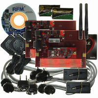
DR-TRC104-2400-DK
Manufacturer Part Number
DR-TRC104-2400-DK
Description
KIT DEV FOR TRC104
Manufacturer
RFM
Type
Transceiverr
Datasheets
1.DR-TRC104-2400-DK.pdf
(33 pages)
2.DR-TRC104-2400-DK.pdf
(1 pages)
3.DR-TRC104-2400-DK.pdf
(2 pages)
Specifications of DR-TRC104-2400-DK
Frequency
2.4GHz
For Use With/related Products
TRC104
Lead Free Status / RoHS Status
Lead free / RoHS Compliant
Other names
583-1137


8.5 RSSI Value
0x04 [default 0x20]
8.6 Data Format Control
0x05 [default 0x0F]
www.RFM.com
©2009 by RF Monolithics, Inc.
Address
Address
0X04
0X05
Name
AGC_En
RSSI_G
RSSI_val
Name
DevAdd_En
DevAdd_pos
DesAdd_ref
FIFO_len
E-mail:
-
info@rfm.com
Bits
Bits
7..6
3..0
4..0
5
4
7
6
5
R/W
R/W
r/w
r/w
r/w
r/w
r/w
r/w
r/w
r/w
Description
Reserved, always set to 00b
Automatic Gain Control Enable (Continuous Mode only):
AGC should be left enabled for most applications
RSSI Gain Mode Selection (Continuous Mode only):
4-bit digital value of RSSI level after A/D conversion.
Description
Insert sender (local device) address in transmit packet (Burst Mode only):
Output received sender address before payload data on receive (Burst Mode only):
Destination address reference (Burst Mode only):
FIFO length (number of payload data bytes, Burst Mode only):
where 0 ≤ FIFO_len ≤ 31
default is 01111b
0 → Disable AGC
1 → Enable AGC
0 → High gain mode
1 → Low gain mode
0 → Insert sender address
1 → Do not insert sender address
0 → Output sender address
1 → Do not output sender address
0 → Registers 0x09 - 0x0D
1 → Provided by the host microcontroller before data is written to FIFO
00000 → 1 byte
00001 → 2 bytes
11111 → 32 bytes
Payload data bytes = FIFO_len + 1
Technical support +1.800.704.6079
…
Table 20
Table 21
TRC104 - 08/13/09
Page 24 of 33
Related parts for DR-TRC104-2400-DK
Image
Part Number
Description
Manufacturer
Datasheet
Request
R

Part Number:
Description:
ASH RX 115.2 KBPS 433.92 MHZ
Manufacturer:
RFM
Datasheet:

Part Number:
Description:
RFIC TRANCEIVER MULTI-CHANNEL FS
Manufacturer:
RFM
Datasheet:

Part Number:
Description:
ASH TX 115.2 KBPS 433.92 MHZ
Manufacturer:
RFM
Datasheet:
Part Number:
Description:
Filters 1602MHz BW=61MHz
Manufacturer:
RFM
Datasheet:

Part Number:
Description:
RESONATOR, SM3030-6
Manufacturer:
RFM
Datasheet:

Part Number:
Description:
RESONATOR, SM3030-6
Manufacturer:
RFM
Datasheet:

Part Number:
Description:
RESONATOR, SM3030-6
Manufacturer:
RFM
Datasheet:

Part Number:
Description:
RESONATOR, SM5035-4
Manufacturer:
RFM
Datasheet:
Part Number:
Description:
RESONATOR 418MHZ SM5035-4
Manufacturer:
RFM
Datasheet:
Part Number:
Description:
RESONATOR 315 MHZ SMD
Manufacturer:
RFM
Datasheet:
Part Number:
Description:
WiFi / 802.11 Modules 2.4 and 5.8GHz + BT
Manufacturer:
RFM
Datasheet:

Part Number:
Description:
10-Terminal Ceramic Surface-Mount Case 7 x 5 mm Nominal Footprint
Manufacturer:
RFM [RF Monolithics, Inc]
Datasheet:
Part Number:
Description:
QUAD-BAND GSM850/GSM/DCS/PCS POWER AMP MODULE
Manufacturer:
RFM [RF Monolithics, Inc]
Datasheet:
Part Number:
Description:
402 to 405 MHz Medical Band Front-end Filter
Manufacturer:
RFM [RF Monolithics, Inc]
Datasheet: