PIC16C782/JW Microchip Technology, PIC16C782/JW Datasheet - Page 74
PIC16C782/JW
Manufacturer Part Number
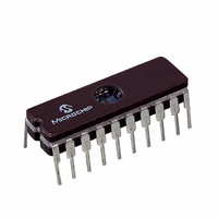
PIC16C782/JW
Description
IC MCU EPROM 2KX14 COMP 20CDIP
Manufacturer
Microchip Technology
Series
PIC® 16Cr
Datasheets
1.PIC16C781-ISO.pdf
(186 pages)
2.PIC16C781-ISO.pdf
(8 pages)
3.PIC16C781-ISO.pdf
(8 pages)
Specifications of PIC16C782/JW
Core Processor
PIC
Core Size
8-Bit
Speed
20MHz
Peripherals
Brown-out Detect/Reset, POR, PWM, WDT
Number Of I /o
13
Program Memory Size
3.5KB (2K x 14)
Program Memory Type
EPROM, UV
Ram Size
128 x 8
Voltage - Supply (vcc/vdd)
4 V ~ 5.5 V
Data Converters
A/D 8x8b; D/A 1x8b
Oscillator Type
Internal
Operating Temperature
0°C ~ 70°C
Package / Case
20-CDIP (0.300", 7.62mm) Window
For Use With
DVA16XP202 - ADAPTER DEVICE PIC16C781/782DM163012 - BOARD DEMO PICDEM FOR 16C781/782AC164028 - MODULE SKT PROMATEII 20SOIC/DIP
Lead Free Status / RoHS Status
Contains lead / RoHS non-compliant
Eeprom Size
-
Connectivity
-
Other names
Q1137459
Available stocks
Company
Part Number
Manufacturer
Quantity
Price


PIC16C781/782
9.2
9.2.1
The ANSEL and TRISB registers control the operation
of the ADC port pins. The port pins to be used as ana-
log inputs must have their corresponding TRISB bits
set (= 1). The proper ANSEL bits must also be set (ana-
log input) to disable the digital input buffer.
TABLE 9-1:
Legend: Shaded cells are outside of recommended range.
Note 1: The RC source has a typical T
DS41171A-page 72
2 T
8 T
32 T
RC
Note 1: The ADC operation is independent of the
OSC
OSC
Operation
OSC
2: These values violate the minimum required T
3: For faster conversion times, the selection of another clock source is recommended.
4: When device frequency is greater than 1 MHz, the RC ADC conversion clock source is recommended for
Configuring the ADC Module
ADC Clock Source (T
2: When reading the PORTA or PORTB reg-
3: Analog levels on any pin that is defined as
SLEEP operation only.
CONFIGURING ANALOG PORT
PINS
state of the TRISB or ANSEL bits. These
bits must be configured by the firmware
prior to initiation of an ADC conversion.
isters, all pins configured as analog input
channels will read as a ‘0’.
a digital input, including AN<7:0>, may
cause the input buffer to consume excess
supply current.
TAD vs. DEVICE OPERATING FREQUENCIES: PIC16C781/782
ADCS1:ADCS0
00
01
10
11
AD
)
AD
time of 4 s.
2 - 6 s
100 ns
20 MHz
400 ns
1.6 s
Preliminary
(1,4)
(2)
AD
time.
9.2.2
The VCFG<5:4> bits in the ADCON1 register configure
the ADC module reference voltage input, ADC
reference input can come from any of the following:
• Internal voltage reference (V
• External comparator C1 reference (V
• DAC output (V
• Analog positive supply (A
If an external reference is chosen for the ADC
the port pin that multiplexes with the incoming external
reference must also be configured as an analog input.
9.2.3
The ADC conversion cycle requires 9.5T
of the ADC conversion clock is software selectable.
The four possible options for ADC clock are:
• F
• F
• F
• ADRC (clock derived from a dedicated internal
For correct ADC conversion, the ADC conversion clock
(T
of 1.6 sec. Table 9-1 shows the resultant T
derived from the device operating frequencies and the
ADC clock source selected.
2 - 6 s
400 ns
AD
RC oscillator)
5 MHz
1.6 s
6.4 s
OSC
OSC
OSC
) must be selected to ensure a minimum T
/2
/8
/32
Device Frequency
(1,4)
(2)
CONFIGURING THE REFERENCE
VOLTAGES
SELECTING THE ADC
CONVERSION CLOCK
DAC
2 - 6 s
1.25 MHz
25.6 s
)
6.4 s
1.6 s
2001 Microchip Technology Inc.
(1,4)
(3)
VDD
R
)
)
333.33kHz
2 - 6 s
REF
24 s
96 s
AD
6 s
. The source
1)
REF
(3)
(3)
AD
REF
(1)
AD
input,
times
. The
time
Related parts for PIC16C782/JW
Image
Part Number
Description
Manufacturer
Datasheet
Request
R

Part Number:
Description:
3.5KB Flash, 128B RAM, 18 I/O, CLC, CWG, DDS, 10-bit ADC 20 QFN 4x4mm TUBE
Manufacturer:
Microchip Technology
Datasheet:

Part Number:
Description:
3.5KB Flash, 128B RAM, 18 I/O, CLC, CWG, DDS, 10-bit ADC 20 PDIP .300in TUBE
Manufacturer:
Microchip Technology
Datasheet:

Part Number:
Description:
3.5KB Flash, 128B RAM, 18 I/O, CLC, CWG, DDS, 10-bit ADC 20 SOIC .300in TUBE
Manufacturer:
Microchip Technology
Datasheet:

Part Number:
Description:
3.5KB Flash, 128B RAM, 18 I/O, CLC, CWG, DDS, 10-bit ADC 20 SSOP .209in TUBE
Manufacturer:
Microchip Technology
Datasheet:
Part Number:
Description:
3.5KB Flash, 128B RAM, 18 I/O, CLC, CWG, DDS, 10-bit ADC 20 QFN 4x4mm TUBE
Manufacturer:
Microchip Technology
Datasheet:
Part Number:
Description:
3.5KB Flash, 128B RAM, 18 I/O, CLC, CWG, DDS, 10-bit ADC 20 PDIP .300in TUBE
Manufacturer:
Microchip Technology
Datasheet:
Part Number:
Description:
3.5KB Flash, 128B RAM, 18 I/O, CLC, CWG, DDS, 10-bit ADC 20 SOIC .300in TUBE
Manufacturer:
Microchip Technology
Datasheet:
Part Number:
Description:
3.5KB Flash, 128B RAM, 18 I/O, CLC, CWG, DDS, 10-bit ADC 20 SSOP .209in TUBE
Manufacturer:
Microchip Technology
Datasheet:
Part Number:
Description:
3.5KB Flash, 128B RAM, 18 I/O, CLC, CWG, DDS, 10-bit ADC 20 QFN 4x4mm T/R
Manufacturer:
Microchip Technology
Datasheet:
Part Number:
Description:
3.5KB Flash, 128B RAM, 18 I/O, CLC, CWG, DDS, 10-bit ADC 20 SOIC .300in T/R
Manufacturer:
Microchip Technology
Datasheet:
Part Number:
Description:
3.5KB Flash, 128B RAM, 18 I/O, CLC, CWG, DDS, 10-bit ADC 20 SSOP .209in T/R
Manufacturer:
Microchip Technology
Datasheet:
Part Number:
Description:
3.5KB Flash, 128B RAM, 18 I/O, CLC, CWG, DDS, 10-bit ADC 20 QFN 4x4mm TUBE
Manufacturer:
Microchip Technology
Datasheet:
Part Number:
Description:
3.5KB Flash, 128B RAM, 18 I/O, CLC, CWG, DDS, 10-bit ADC 20 PDIP .300in TUBE
Manufacturer:
Microchip Technology
Datasheet:
Part Number:
Description:
3.5KB Flash, 128B RAM, 18 I/O, CLC, CWG, DDS, 10-bit ADC 20 SOIC .300in TUBE
Manufacturer:
Microchip Technology
Datasheet:
Part Number:
Description:
3.5KB Flash, 128B RAM, 18 I/O, CLC, CWG, DDS, 10-bit ADC 20 SSOP .209in TUBE
Manufacturer:
Microchip Technology
Datasheet: