PIC16C782/JW Microchip Technology, PIC16C782/JW Datasheet - Page 69
PIC16C782/JW
Manufacturer Part Number
PIC16C782/JW
Description
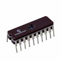
IC MCU EPROM 2KX14 COMP 20CDIP
Manufacturer
Microchip Technology
Series
PIC® 16Cr
Datasheets
1.PIC16C781-ISO.pdf
(186 pages)
2.PIC16C781-ISO.pdf
(8 pages)
3.PIC16C781-ISO.pdf
(8 pages)
Specifications of PIC16C782/JW
Core Processor
PIC
Core Size
8-Bit
Speed
20MHz
Peripherals
Brown-out Detect/Reset, POR, PWM, WDT
Number Of I /o
13
Program Memory Size
3.5KB (2K x 14)
Program Memory Type
EPROM, UV
Ram Size
128 x 8
Voltage - Supply (vcc/vdd)
4 V ~ 5.5 V
Data Converters
A/D 8x8b; D/A 1x8b
Oscillator Type
Internal
Operating Temperature
0°C ~ 70°C
Package / Case
20-CDIP (0.300", 7.62mm) Window
For Use With
DVA16XP202 - ADAPTER DEVICE PIC16C781/782DM163012 - BOARD DEMO PICDEM FOR 16C781/782AC164028 - MODULE SKT PROMATEII 20SOIC/DIP
Lead Free Status / RoHS Status
Contains lead / RoHS non-compliant
Eeprom Size
-
Connectivity
-
Other names
Q1137459
Available stocks
Company
Part Number
Manufacturer
Quantity
Price


Example 8-1 shows the configuration of the PLVD mod-
ule and a sample polling routine to monitor for low volt-
age conditions.
EXAMPLE 8-1:
;************************************************
;*
;*
;*
;*
WRM_UP
;**************************************************
;* Test for PLVD trip
8.3
When enabled, the PLVD circuitry continues to operate
during SLEEP. If the device voltage crosses the trip
point, the LVDIF bit is set and the device awakens from
SLEEP. Device execution continues from the interrupt
vector address, if interrupts have been globally
enabled.
TABLE 8-1:
09Ch
08Ch
08Ch
Address
2001 Microchip Technology Inc.
This code block will configure the PLVD for polling
and set the trip point for 4.2 to 4.4 volts
Includes polling routine
BANKSEL
BCF
MOVLW
MOVWF
BTFSS
GOTO
BANKSEL
BCF
BANKSEL
BTFSC
GOTO
Operation During SLEEP
PIE1
PIR1
LVDCON
Name
LVDCON
PIE1,LVDIE
B’00011101’
LVDCON
LVDCON,BGST
WRM_UP
PIR1
PIR1,LVDIF
PIR1
PIR1,LVDIF
LO_V_DET
SUMMARY OF REGISTERS ASSOCIATED WITH LOW VOLTAGE DETECT
LVDIE
LVDIF
Bit 7
PLVD EXAMPLE
—
ADIE
ADIF
Bit 6
—
BGST
C2IE
Bit 5
C2IF
; Select Bank 1
; Disable PLVD interrupt
; Enable PLVD, 4.2-4.4V trip
;
;
; Select Bank 0
; Clear PLVD interrupt flag
; Select Bank 0
; Test for PLVD trip
; If tripped save 4 pwrfail
LVDEN
Bit 4
C2IE
C2IF
Preliminary
Bit 3
LV3
—
—
8.4
A device RESET forces all registers to their RESET
state. This forces the PLVD module to be disabled.
8.5
The registers associated with Programmable Low Volt-
age Detect are shown in Table 8-1.
Bit 2
LV2
—
—
Effects of a RESET
Low Voltage Detect Registers
Bit 1
LV1
—
—
PIC16C781/782
TMR1IE
TMR1IF
Bit 0
LV0
--00 0101
0000 ---0
0000 ---0
POR, BOR
Value on:
DS41171A-page 67
--00 0101
0000 ---0
0000 ---0
Value on
all other
RESETS
Related parts for PIC16C782/JW
Image
Part Number
Description
Manufacturer
Datasheet
Request
R

Part Number:
Description:
3.5KB Flash, 128B RAM, 18 I/O, CLC, CWG, DDS, 10-bit ADC 20 QFN 4x4mm TUBE
Manufacturer:
Microchip Technology
Datasheet:

Part Number:
Description:
3.5KB Flash, 128B RAM, 18 I/O, CLC, CWG, DDS, 10-bit ADC 20 PDIP .300in TUBE
Manufacturer:
Microchip Technology
Datasheet:

Part Number:
Description:
3.5KB Flash, 128B RAM, 18 I/O, CLC, CWG, DDS, 10-bit ADC 20 SOIC .300in TUBE
Manufacturer:
Microchip Technology
Datasheet:

Part Number:
Description:
3.5KB Flash, 128B RAM, 18 I/O, CLC, CWG, DDS, 10-bit ADC 20 SSOP .209in TUBE
Manufacturer:
Microchip Technology
Datasheet:
Part Number:
Description:
3.5KB Flash, 128B RAM, 18 I/O, CLC, CWG, DDS, 10-bit ADC 20 QFN 4x4mm TUBE
Manufacturer:
Microchip Technology
Datasheet:
Part Number:
Description:
3.5KB Flash, 128B RAM, 18 I/O, CLC, CWG, DDS, 10-bit ADC 20 PDIP .300in TUBE
Manufacturer:
Microchip Technology
Datasheet:
Part Number:
Description:
3.5KB Flash, 128B RAM, 18 I/O, CLC, CWG, DDS, 10-bit ADC 20 SOIC .300in TUBE
Manufacturer:
Microchip Technology
Datasheet:
Part Number:
Description:
3.5KB Flash, 128B RAM, 18 I/O, CLC, CWG, DDS, 10-bit ADC 20 SSOP .209in TUBE
Manufacturer:
Microchip Technology
Datasheet:
Part Number:
Description:
3.5KB Flash, 128B RAM, 18 I/O, CLC, CWG, DDS, 10-bit ADC 20 QFN 4x4mm T/R
Manufacturer:
Microchip Technology
Datasheet:
Part Number:
Description:
3.5KB Flash, 128B RAM, 18 I/O, CLC, CWG, DDS, 10-bit ADC 20 SOIC .300in T/R
Manufacturer:
Microchip Technology
Datasheet:
Part Number:
Description:
3.5KB Flash, 128B RAM, 18 I/O, CLC, CWG, DDS, 10-bit ADC 20 SSOP .209in T/R
Manufacturer:
Microchip Technology
Datasheet:
Part Number:
Description:
3.5KB Flash, 128B RAM, 18 I/O, CLC, CWG, DDS, 10-bit ADC 20 QFN 4x4mm TUBE
Manufacturer:
Microchip Technology
Datasheet:
Part Number:
Description:
3.5KB Flash, 128B RAM, 18 I/O, CLC, CWG, DDS, 10-bit ADC 20 PDIP .300in TUBE
Manufacturer:
Microchip Technology
Datasheet:
Part Number:
Description:
3.5KB Flash, 128B RAM, 18 I/O, CLC, CWG, DDS, 10-bit ADC 20 SOIC .300in TUBE
Manufacturer:
Microchip Technology
Datasheet:
Part Number:
Description:
3.5KB Flash, 128B RAM, 18 I/O, CLC, CWG, DDS, 10-bit ADC 20 SSOP .209in TUBE
Manufacturer:
Microchip Technology
Datasheet: