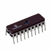
PIC16C782/JW Microchip Technology, PIC16C782/JW Datasheet - Page 27

PIC16C782/JW
Manufacturer Part Number
PIC16C782/JW
Description
IC MCU EPROM 2KX14 COMP 20CDIP
Manufacturer
Microchip Technology
Series
PIC® 16Cr
Datasheets
1.PIC16C781-ISO.pdf
(186 pages)
2.PIC16C781-ISO.pdf
(8 pages)
3.PIC16C781-ISO.pdf
(8 pages)
Specifications of PIC16C782/JW
Core Processor
PIC
Core Size
8-Bit
Speed
20MHz
Peripherals
Brown-out Detect/Reset, POR, PWM, WDT
Number Of I /o
13
Program Memory Size
3.5KB (2K x 14)
Program Memory Type
EPROM, UV
Ram Size
128 x 8
Voltage - Supply (vcc/vdd)
4 V ~ 5.5 V
Data Converters
A/D 8x8b; D/A 1x8b
Oscillator Type
Internal
Operating Temperature
0°C ~ 70°C
Package / Case
20-CDIP (0.300", 7.62mm) Window
For Use With
DVA16XP202 - ADAPTER DEVICE PIC16C781/782DM163012 - BOARD DEMO PICDEM FOR 16C781/782AC164028 - MODULE SKT PROMATEII 20SOIC/DIP
Lead Free Status / RoHS Status
Contains lead / RoHS non-compliant
Eeprom Size
-
Connectivity
-
Other names
Q1137459
Available stocks
Company
Part Number
Manufacturer
Quantity
Price
- Current page: 27 of 186
- Download datasheet (4Mb)
3.0
Most pins for the I/O ports are multiplexed with an alter-
nate function for the peripheral features on the device.
In general, when a peripheral is enabled, that pin may
not be used as a general purpose I/O pin.
Additional information on I/O ports may be found in the
PICmicro™ Mid-Range Reference Manual (DS33023)
3.1
The PIC16C781/782 has two I/O ports: PORTA and
PORTB. Some of these port pins are mixed signal (can
be digital or analog). When an analog signal is present
on a pin, the pin must be configured as an analog input
REGISTER 3-1:
2001 Microchip Technology Inc.
I/O PORTS
I/O Port Analog/Digital Mode
bit 7-0
bit 7
ANS<7:0>: Select Analog Input Function on AN<7:0> bits
1 = Analog input
0 = Digital I/O
Legend:
R = Readable bit
- n = Value at POR
ANALOG SELECT REGISTER (ANSEL: 9Dh)
Note:
R/W-1
ANS7
Setting a pin to an analog input disables the digital input buffer. The corresponding
TRIS bit should be set to input mode when using pins as analog inputs.
R/W-1
ANS6
R/W-1
ANS5
Preliminary
W = Writable bit
’1’ = Bit is set
R/W-1
ANS4
to prevent unnecessary current drawn from the power
supply. The Analog Select register (ANSEL) allows the
user to individually select the Digital/Analog mode on
these pins. When the Analog mode is active, the port
pin always reads as a logic 0.
Note 1: On a Power-on Reset, the ANSEL regis-
R/W-1
ANS3
U = Unimplemented bit, read as ‘0’
’0’ = Bit is cleared
2: If a pin is configured as Analog mode, the
ter configures these mixed signal pins as
Analog mode: RA<3:0>, RB<3:0>.
pin always reads '0', even if the digital out-
put is active.
PIC16C781/782
R/W-1
ANS2
x = Bit is unknown
R/W-1
ANS1
DS41171A-page 25
R/W-1
ANS0
bit 0
Related parts for PIC16C782/JW
Image
Part Number
Description
Manufacturer
Datasheet
Request
R

Part Number:
Description:
3.5KB Flash, 128B RAM, 18 I/O, CLC, CWG, DDS, 10-bit ADC 20 QFN 4x4mm TUBE
Manufacturer:
Microchip Technology
Datasheet:

Part Number:
Description:
3.5KB Flash, 128B RAM, 18 I/O, CLC, CWG, DDS, 10-bit ADC 20 PDIP .300in TUBE
Manufacturer:
Microchip Technology
Datasheet:

Part Number:
Description:
3.5KB Flash, 128B RAM, 18 I/O, CLC, CWG, DDS, 10-bit ADC 20 SOIC .300in TUBE
Manufacturer:
Microchip Technology
Datasheet:

Part Number:
Description:
3.5KB Flash, 128B RAM, 18 I/O, CLC, CWG, DDS, 10-bit ADC 20 SSOP .209in TUBE
Manufacturer:
Microchip Technology
Datasheet:

Part Number:
Description:
3.5KB Flash, 128B RAM, 18 I/O, CLC, CWG, DDS, 10-bit ADC 20 QFN 4x4mm TUBE
Manufacturer:
Microchip Technology
Datasheet:

Part Number:
Description:
3.5KB Flash, 128B RAM, 18 I/O, CLC, CWG, DDS, 10-bit ADC 20 PDIP .300in TUBE
Manufacturer:
Microchip Technology
Datasheet:

Part Number:
Description:
3.5KB Flash, 128B RAM, 18 I/O, CLC, CWG, DDS, 10-bit ADC 20 SOIC .300in TUBE
Manufacturer:
Microchip Technology
Datasheet:

Part Number:
Description:
3.5KB Flash, 128B RAM, 18 I/O, CLC, CWG, DDS, 10-bit ADC 20 SSOP .209in TUBE
Manufacturer:
Microchip Technology
Datasheet:

Part Number:
Description:
3.5KB Flash, 128B RAM, 18 I/O, CLC, CWG, DDS, 10-bit ADC 20 QFN 4x4mm T/R
Manufacturer:
Microchip Technology
Datasheet:

Part Number:
Description:
3.5KB Flash, 128B RAM, 18 I/O, CLC, CWG, DDS, 10-bit ADC 20 SOIC .300in T/R
Manufacturer:
Microchip Technology
Datasheet:

Part Number:
Description:
3.5KB Flash, 128B RAM, 18 I/O, CLC, CWG, DDS, 10-bit ADC 20 SSOP .209in T/R
Manufacturer:
Microchip Technology
Datasheet:

Part Number:
Description:
3.5KB Flash, 128B RAM, 18 I/O, CLC, CWG, DDS, 10-bit ADC 20 QFN 4x4mm TUBE
Manufacturer:
Microchip Technology
Datasheet:

Part Number:
Description:
3.5KB Flash, 128B RAM, 18 I/O, CLC, CWG, DDS, 10-bit ADC 20 PDIP .300in TUBE
Manufacturer:
Microchip Technology
Datasheet:

Part Number:
Description:
3.5KB Flash, 128B RAM, 18 I/O, CLC, CWG, DDS, 10-bit ADC 20 SOIC .300in TUBE
Manufacturer:
Microchip Technology
Datasheet:

Part Number:
Description:
3.5KB Flash, 128B RAM, 18 I/O, CLC, CWG, DDS, 10-bit ADC 20 SSOP .209in TUBE
Manufacturer:
Microchip Technology
Datasheet:


