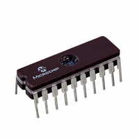
PIC16C782/JW Microchip Technology, PIC16C782/JW Datasheet - Page 61

PIC16C782/JW
Manufacturer Part Number
PIC16C782/JW
Description
IC MCU EPROM 2KX14 COMP 20CDIP
Manufacturer
Microchip Technology
Series
PIC® 16Cr
Datasheets
1.PIC16C781-ISO.pdf
(186 pages)
2.PIC16C781-ISO.pdf
(8 pages)
3.PIC16C781-ISO.pdf
(8 pages)
Specifications of PIC16C782/JW
Core Processor
PIC
Core Size
8-Bit
Speed
20MHz
Peripherals
Brown-out Detect/Reset, POR, PWM, WDT
Number Of I /o
13
Program Memory Size
3.5KB (2K x 14)
Program Memory Type
EPROM, UV
Ram Size
128 x 8
Voltage - Supply (vcc/vdd)
4 V ~ 5.5 V
Data Converters
A/D 8x8b; D/A 1x8b
Oscillator Type
Internal
Operating Temperature
0°C ~ 70°C
Package / Case
20-CDIP (0.300", 7.62mm) Window
For Use With
DVA16XP202 - ADAPTER DEVICE PIC16C781/782DM163012 - BOARD DEMO PICDEM FOR 16C781/782AC164028 - MODULE SKT PROMATEII 20SOIC/DIP
Lead Free Status / RoHS Status
Contains lead / RoHS non-compliant
Eeprom Size
-
Connectivity
-
Other names
Q1137459
Available stocks
Company
Part Number
Manufacturer
Quantity
Price
- Current page: 61 of 186
- Download datasheet (4Mb)
6.3
When the microcontroller is using INTRC w/o CLKOUT,
Timer1 can enable and use the LP oscillator as the
Timer1 oscillator.
operation is solely controlled by the T1OSCEN bit. The
oscillator will operate independently of the TMR1ON
bit, allowing the programmer to start and stop the
Timer/Counter using the TMR1ON bit. The oscillator
will also operate during SLEEP, allowing continuous
timekeeping with Timer1. The electrical requirements
for the LP oscillator, when used as the Timer1 oscilla-
tor, are the same as when the oscillator is used in LP
mode.
TABLE 6-1:
0Bh
0Ch
8Ch
0Eh
0Fh
10h
Legend: x = unknown, u = unchanged, - = unimplemented, read as '0'. Shaded cells are not used by Timer1.
Address
Note:
2001 Microchip Technology Inc.
Timer1 Oscillator for the
PIC16C781/782
INTCON
PIR1
PIE1
TMR1L
TMR1H
T1CON
Name
The oscillator requires a startup and stabi-
lization
T1OSCEN should be set, and a suitable
delay observed, prior to enabling Timer1
(see Section 14.2).
SUMMARY OF REGISTERS ASSOCIATED WITH TIMER1
Least Significant Byte of the 16-bit TMR1 Register
Most Significant Byte of the 16-bit TMR1 Register
LVDIF
LVDIE
Bit 7
When enabled, Timer1 oscillator
GIE
time
—
TMR1GE T1CKPS1 T1CKPS0 T1OSCEN T1SYNC TMR1CS TMR1ON -000 0000 -uuu uuuu
before
PEIE
ADIF
ADIE
Bit 6
use.
C2IE
Bit 5
T0IE
C2IF
Therefore,
INTE
C1IE
Bit 4
C1IF
Preliminary
RBIE
Bit 3
—
—
6.4
The TMR1 register pair (TMR1H and TMR1L) incre-
ments from 0000h to FFFFh and then rolls over to
0000h. When Timer1 rolls over, the TMR1IF bit
(PIR1<0>) is set. To enable an interrupt, the TMR1IE
bit (PIE1<0>), the GIE (INTCON<7>) and the PEIE bit
(INTCON<6>) must be set prior to rollover. To clear the
interrupt, the TMR1IF must be cleared by software prior
to re-enabling interrupts.
6.5
Only POR and BOR Resets clear T1CON, disabling
Timer1. All other RESETS do not affect Timer1.
Note:
Bit 2
T0IF
—
—
Timer1 Interrupt
Effects of RESET
When enabling the Timer1 interrupt, the
user should clear both TMR1 registers and
the TMR1IF prior to enabling interrupts.
PIC16C781/782
Bit 1
INTF
—
—
TMRIE
TMRIF
RBIF
Bit 0
0000 000X 0000 000u
0000 ---0 0000 ---0
0000 ---0 0000 ---0
xxxx xxxx uuuu uuuu
xxxx xxxx uuuu uuuu
Value on:
POR,
BOR
DS41171A-page 59
Value on
RESETS
all other
Related parts for PIC16C782/JW
Image
Part Number
Description
Manufacturer
Datasheet
Request
R

Part Number:
Description:
3.5KB Flash, 128B RAM, 18 I/O, CLC, CWG, DDS, 10-bit ADC 20 QFN 4x4mm TUBE
Manufacturer:
Microchip Technology
Datasheet:

Part Number:
Description:
3.5KB Flash, 128B RAM, 18 I/O, CLC, CWG, DDS, 10-bit ADC 20 PDIP .300in TUBE
Manufacturer:
Microchip Technology
Datasheet:

Part Number:
Description:
3.5KB Flash, 128B RAM, 18 I/O, CLC, CWG, DDS, 10-bit ADC 20 SOIC .300in TUBE
Manufacturer:
Microchip Technology
Datasheet:

Part Number:
Description:
3.5KB Flash, 128B RAM, 18 I/O, CLC, CWG, DDS, 10-bit ADC 20 SSOP .209in TUBE
Manufacturer:
Microchip Technology
Datasheet:

Part Number:
Description:
3.5KB Flash, 128B RAM, 18 I/O, CLC, CWG, DDS, 10-bit ADC 20 QFN 4x4mm TUBE
Manufacturer:
Microchip Technology
Datasheet:

Part Number:
Description:
3.5KB Flash, 128B RAM, 18 I/O, CLC, CWG, DDS, 10-bit ADC 20 PDIP .300in TUBE
Manufacturer:
Microchip Technology
Datasheet:

Part Number:
Description:
3.5KB Flash, 128B RAM, 18 I/O, CLC, CWG, DDS, 10-bit ADC 20 SOIC .300in TUBE
Manufacturer:
Microchip Technology
Datasheet:

Part Number:
Description:
3.5KB Flash, 128B RAM, 18 I/O, CLC, CWG, DDS, 10-bit ADC 20 SSOP .209in TUBE
Manufacturer:
Microchip Technology
Datasheet:

Part Number:
Description:
3.5KB Flash, 128B RAM, 18 I/O, CLC, CWG, DDS, 10-bit ADC 20 QFN 4x4mm T/R
Manufacturer:
Microchip Technology
Datasheet:

Part Number:
Description:
3.5KB Flash, 128B RAM, 18 I/O, CLC, CWG, DDS, 10-bit ADC 20 SOIC .300in T/R
Manufacturer:
Microchip Technology
Datasheet:

Part Number:
Description:
3.5KB Flash, 128B RAM, 18 I/O, CLC, CWG, DDS, 10-bit ADC 20 SSOP .209in T/R
Manufacturer:
Microchip Technology
Datasheet:

Part Number:
Description:
3.5KB Flash, 128B RAM, 18 I/O, CLC, CWG, DDS, 10-bit ADC 20 QFN 4x4mm TUBE
Manufacturer:
Microchip Technology
Datasheet:

Part Number:
Description:
3.5KB Flash, 128B RAM, 18 I/O, CLC, CWG, DDS, 10-bit ADC 20 PDIP .300in TUBE
Manufacturer:
Microchip Technology
Datasheet:

Part Number:
Description:
3.5KB Flash, 128B RAM, 18 I/O, CLC, CWG, DDS, 10-bit ADC 20 SOIC .300in TUBE
Manufacturer:
Microchip Technology
Datasheet:

Part Number:
Description:
3.5KB Flash, 128B RAM, 18 I/O, CLC, CWG, DDS, 10-bit ADC 20 SSOP .209in TUBE
Manufacturer:
Microchip Technology
Datasheet:


