PIC16C782/JW Microchip Technology, PIC16C782/JW Datasheet - Page 112
PIC16C782/JW
Manufacturer Part Number
PIC16C782/JW
Description
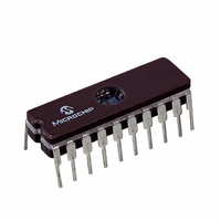
IC MCU EPROM 2KX14 COMP 20CDIP
Manufacturer
Microchip Technology
Series
PIC® 16Cr
Datasheets
1.PIC16C781-ISO.pdf
(186 pages)
2.PIC16C781-ISO.pdf
(8 pages)
3.PIC16C781-ISO.pdf
(8 pages)
Specifications of PIC16C782/JW
Core Processor
PIC
Core Size
8-Bit
Speed
20MHz
Peripherals
Brown-out Detect/Reset, POR, PWM, WDT
Number Of I /o
13
Program Memory Size
3.5KB (2K x 14)
Program Memory Type
EPROM, UV
Ram Size
128 x 8
Voltage - Supply (vcc/vdd)
4 V ~ 5.5 V
Data Converters
A/D 8x8b; D/A 1x8b
Oscillator Type
Internal
Operating Temperature
0°C ~ 70°C
Package / Case
20-CDIP (0.300", 7.62mm) Window
For Use With
DVA16XP202 - ADAPTER DEVICE PIC16C781/782DM163012 - BOARD DEMO PICDEM FOR 16C781/782AC164028 - MODULE SKT PROMATEII 20SOIC/DIP
Lead Free Status / RoHS Status
Contains lead / RoHS non-compliant
Eeprom Size
-
Connectivity
-
Other names
Q1137459
Available stocks
Company
Part Number
Manufacturer
Quantity
Price


PIC16C781/782
13.3.2
In this example, the PSMC controls the buck configura-
tion switching power supply in Figure 13-6.
The PSMC is configured as a typical PWM, current
mode, switching power supply controller. The inner cur-
rent feedback loops consist of:
• PSMC
• 2 MOSFET drivers
• Power MOSFETs Q1 and Q2
• Inductors L1 and L2
• Current transformer
• Comparator C1/C2
The outer voltage feedback loop consists of:
• Diodes D1, D2, D3, and D4
• C
• OPAMP feedback filter
• DAC reference
The circuit uses two feedback loops, an inner current
control loop, and an outer voltage loop. The inner loop
is further divided into two channels, Q1/L1, and Q2/L2.
The PSMC operates a PWM output, alternately driving
Q1 for a cycle, then driving Q2 the next. During the
active phase of either output pulse, the inner loop
builds up a current flow in the output’s inductor, propor-
tional to the error voltage received from the OPAMP.
The current flow in the inductor begins the charging of
C
flow in the inductor) exceeds the error voltage:
• The comparator resets the PSMC output
• The MOSFET is turned off
• The flyback diode forward biases
• The inductor discharges into C
DS41171A-page 110
MAIN
remainder of the period.
MAIN
. When the voltage (proportional to the current
EXAMPLE BUCK LC SWITCHING
POWER SUPPLY
MAIN
for the
Preliminary
The outer voltage loop monitors the output voltage
across C
the DAC is subtracted from the feedback voltage to
generate the raw error voltage. The raw error voltage is
then filtered by the OPAMP and routed to Comparator
C1 in the inner current loop.
In using two alternating outputs, the outputs are limited
to less than 50% duty cycle. As a result, the circuit
avoids the problems associated with instability at duty
cycles of >50%.
For more information concerning the design of switch-
ing power supplies, refer to:
Switching Power Supply Design, by Abraham I. Press-
man, published by McGraw Hill (ISBN 0-07-052236-7).
Note:
MAIN
Following RESET, both the PSMC1A and
PSMC1B outputs are held tri-state until the
PSMC is configured. Driver circuitry for all
power MOSFET transistors must have a
resistor bias to turn off the transistor in the
event of tri-state conditions on either out-
put to prevent undo stress on the MOS-
FET's and their associated circuitry.
via R1/R2. The reference voltage from
2001 Microchip Technology Inc.
Related parts for PIC16C782/JW
Image
Part Number
Description
Manufacturer
Datasheet
Request
R

Part Number:
Description:
3.5KB Flash, 128B RAM, 18 I/O, CLC, CWG, DDS, 10-bit ADC 20 QFN 4x4mm TUBE
Manufacturer:
Microchip Technology
Datasheet:

Part Number:
Description:
3.5KB Flash, 128B RAM, 18 I/O, CLC, CWG, DDS, 10-bit ADC 20 PDIP .300in TUBE
Manufacturer:
Microchip Technology
Datasheet:

Part Number:
Description:
3.5KB Flash, 128B RAM, 18 I/O, CLC, CWG, DDS, 10-bit ADC 20 SOIC .300in TUBE
Manufacturer:
Microchip Technology
Datasheet:

Part Number:
Description:
3.5KB Flash, 128B RAM, 18 I/O, CLC, CWG, DDS, 10-bit ADC 20 SSOP .209in TUBE
Manufacturer:
Microchip Technology
Datasheet:
Part Number:
Description:
3.5KB Flash, 128B RAM, 18 I/O, CLC, CWG, DDS, 10-bit ADC 20 QFN 4x4mm TUBE
Manufacturer:
Microchip Technology
Datasheet:
Part Number:
Description:
3.5KB Flash, 128B RAM, 18 I/O, CLC, CWG, DDS, 10-bit ADC 20 PDIP .300in TUBE
Manufacturer:
Microchip Technology
Datasheet:
Part Number:
Description:
3.5KB Flash, 128B RAM, 18 I/O, CLC, CWG, DDS, 10-bit ADC 20 SOIC .300in TUBE
Manufacturer:
Microchip Technology
Datasheet:
Part Number:
Description:
3.5KB Flash, 128B RAM, 18 I/O, CLC, CWG, DDS, 10-bit ADC 20 SSOP .209in TUBE
Manufacturer:
Microchip Technology
Datasheet:
Part Number:
Description:
3.5KB Flash, 128B RAM, 18 I/O, CLC, CWG, DDS, 10-bit ADC 20 QFN 4x4mm T/R
Manufacturer:
Microchip Technology
Datasheet:
Part Number:
Description:
3.5KB Flash, 128B RAM, 18 I/O, CLC, CWG, DDS, 10-bit ADC 20 SOIC .300in T/R
Manufacturer:
Microchip Technology
Datasheet:
Part Number:
Description:
3.5KB Flash, 128B RAM, 18 I/O, CLC, CWG, DDS, 10-bit ADC 20 SSOP .209in T/R
Manufacturer:
Microchip Technology
Datasheet:
Part Number:
Description:
3.5KB Flash, 128B RAM, 18 I/O, CLC, CWG, DDS, 10-bit ADC 20 QFN 4x4mm TUBE
Manufacturer:
Microchip Technology
Datasheet:
Part Number:
Description:
3.5KB Flash, 128B RAM, 18 I/O, CLC, CWG, DDS, 10-bit ADC 20 PDIP .300in TUBE
Manufacturer:
Microchip Technology
Datasheet:
Part Number:
Description:
3.5KB Flash, 128B RAM, 18 I/O, CLC, CWG, DDS, 10-bit ADC 20 SOIC .300in TUBE
Manufacturer:
Microchip Technology
Datasheet:
Part Number:
Description:
3.5KB Flash, 128B RAM, 18 I/O, CLC, CWG, DDS, 10-bit ADC 20 SSOP .209in TUBE
Manufacturer:
Microchip Technology
Datasheet: