PIC16C782/JW Microchip Technology, PIC16C782/JW Datasheet - Page 178
PIC16C782/JW
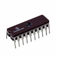
Manufacturer Part Number
PIC16C782/JW
Description
IC MCU EPROM 2KX14 COMP 20CDIP
Manufacturer
Microchip Technology
Series
PIC® 16Cr
Datasheets
1.PIC16C781-ISO.pdf
(186 pages)
2.PIC16C781-ISO.pdf
(8 pages)
3.PIC16C781-ISO.pdf
(8 pages)
Specifications of PIC16C782/JW
Core Processor
PIC
Core Size
8-Bit
Speed
20MHz
Peripherals
Brown-out Detect/Reset, POR, PWM, WDT
Number Of I /o
13
Program Memory Size
3.5KB (2K x 14)
Program Memory Type
EPROM, UV
Ram Size
128 x 8
Voltage - Supply (vcc/vdd)
4 V ~ 5.5 V
Data Converters
A/D 8x8b; D/A 1x8b
Oscillator Type
Internal
Operating Temperature
0°C ~ 70°C
Package / Case
20-CDIP (0.300", 7.62mm) Window
For Use With
DVA16XP202 - ADAPTER DEVICE PIC16C781/782DM163012 - BOARD DEMO PICDEM FOR 16C781/782AC164028 - MODULE SKT PROMATEII 20SOIC/DIP
Lead Free Status / RoHS Status
Contains lead / RoHS non-compliant
Eeprom Size
-
Connectivity
-
Other names
Q1137459
Available stocks
Company
Part Number
Manufacturer
Quantity
Price


PIC16C781/782
E
EC Mode ........................................................................... 119
Effect of RESET on Core Registers .................................... 24
Effects of RESET ................................................................ 52
Electrical Characteristics................................................... 147
Errata .................................................................................... 3
Examples
External Power-on Reset Circuit ....................................... 122
F
Firmware Instructions........................................................ 133
FSR Register....................................................................... 15
G
General Purpose Register File............................................ 13
I
I/O Port Analog/Digital Mode............................................... 25
I/O Ports .............................................................................. 25
ICEPIC In-Circuit Emulator ............................................... 142
ID Locations ...................................................................... 117
In-Circuit Serial Programming (ICSP) ............................... 117
Indirect Addressing ............................................................. 24
Initialization Condition for All Registers............................. 126
Initializing Timer0 ................................................................ 51
Instruction Format ............................................................. 133
Instruction Set ................................................................... 133
DS41171A-page 176
Summary..................................................................... 24
DAC Configuration ...................................................... 81
OPAMP Calibration Mode Configuration..................... 86
Peripheral Configuration ........................................... 113
PSMC Configuration ................................................. 109
PSMC Configuration Example for a Buck
Mode Switching Power Supply ................................. 111
Window Comparator ................................................... 97
ADDLW ..................................................................... 135
ADDWF ..................................................................... 135
ANDLW ..................................................................... 135
ANDWF ..................................................................... 135
BCF ........................................................................... 135
BSF ........................................................................... 135
BTFSC ...................................................................... 136
BTFSS ...................................................................... 135
CALL ......................................................................... 136
CLRF......................................................................... 136
CLRW........................................................................ 136
CLRWDT................................................................... 136
COMF ....................................................................... 136
DECF ........................................................................ 136
DECFSZ.................................................................... 137
GOTO........................................................................ 137
INCF.......................................................................... 137
INCFSZ ..................................................................... 137
IORLW....................................................................... 137
IORWF ...................................................................... 137
MOVF........................................................................ 138
MOVLW..................................................................... 138
MOVWF .................................................................... 138
NOP .......................................................................... 138
RETFIE ..................................................................... 138
RETLW...................................................................... 138
RETURN ................................................................... 138
RLF ........................................................................... 138
RRF........................................................................... 139
SLEEP ...................................................................... 139
Preliminary
INT Interrupt (RB0/INT/AN4/VR). See Interrupt Sources
INTCON Register
Interrupt Sources ...................................................... 117, 128
Interrupts, Context Saving During..................................... 129
Interrupts, Enable Bits
Interrupts, Flag Bits
K
K
L
Low Power Window Comparator with Interrupt .................. 96
Low Voltage Detect
Low Voltage Detect Registers ............................................ 67
Low Voltage Detect Waveforms ......................................... 65
LP, XT and HS Modes ...................................................... 119
M
Master Clear (MCLR)
Memory Organization ......................................................... 11
MPLAB C17 and MPLAB C18 C Compilers ..................... 141
MPLAB ICD In-Circuit Debugger ...................................... 143
MPLAB ICE High Performance Universal
In-Circuit Emulator with MPLAB IDE ................................ 142
MPLAB Integrated Development
Environment Software ...................................................... 141
MPLINK Object Linker/MPLIB Object Librarian ................ 142
O
OPA Auto Calibration.......................................................... 83
OPA Module
OPA Offset Voltage ............................................................ 84
OPCODE Field Descriptions............................................. 133
Operational Amplifier (OPA) Module .................................. 83
EE
L
SUBLW ..................................................................... 139
SUBWF..................................................................... 139
SWAPF ..................................................................... 139
XORLW..................................................................... 139
XORWF .................................................................... 140
GIE Bit ........................................................................ 19
INTE Bit ...................................................................... 19
INTF Bit ...................................................................... 19
PEIE Bit ...................................................................... 19
RBIE Bit ...................................................................... 19
RBIF Bit ...................................................................... 19
T0IE Bit ....................................................................... 19
T0IF Bit ....................................................................... 19
RB0/INT Pin, External............................................... 128
TMR0 Overflow................................................... 52, 129
Global Interrupt Enable (GIE Bit) .............................. 128
Interrupt-on-Change (RB7:RB0) Enable
(RBIE Bit).................................................................. 129
Interrupt-on-Change (RB7:RB4) Flag
(RBIF Bit) .................................................................. 129
TMR0 Overflow Flag (T0IF Bit)................................. 129
Associated Register Summary ................................... 67
MCLR Reset, Normal Operation....................... 125, 126
MCLR Reset, SLEEP................................ 121, 125, 126
Associated Registers .................................................. 87
Common Mode Voltage Range................................... 86
Effects of a RESET ..................................................... 86
Gain Bandwidth Product ............................................. 86
Input Offset Voltage .................................................... 86
Leakage Current ......................................................... 86
Open Loop Gain ......................................................... 86
OQ
Evaluation and Programming Tools .................... 144
2001 Microchip Technology Inc.
Related parts for PIC16C782/JW
Image
Part Number
Description
Manufacturer
Datasheet
Request
R

Part Number:
Description:
3.5KB Flash, 128B RAM, 18 I/O, CLC, CWG, DDS, 10-bit ADC 20 QFN 4x4mm TUBE
Manufacturer:
Microchip Technology
Datasheet:

Part Number:
Description:
3.5KB Flash, 128B RAM, 18 I/O, CLC, CWG, DDS, 10-bit ADC 20 PDIP .300in TUBE
Manufacturer:
Microchip Technology
Datasheet:

Part Number:
Description:
3.5KB Flash, 128B RAM, 18 I/O, CLC, CWG, DDS, 10-bit ADC 20 SOIC .300in TUBE
Manufacturer:
Microchip Technology
Datasheet:

Part Number:
Description:
3.5KB Flash, 128B RAM, 18 I/O, CLC, CWG, DDS, 10-bit ADC 20 SSOP .209in TUBE
Manufacturer:
Microchip Technology
Datasheet:
Part Number:
Description:
3.5KB Flash, 128B RAM, 18 I/O, CLC, CWG, DDS, 10-bit ADC 20 QFN 4x4mm TUBE
Manufacturer:
Microchip Technology
Datasheet:
Part Number:
Description:
3.5KB Flash, 128B RAM, 18 I/O, CLC, CWG, DDS, 10-bit ADC 20 PDIP .300in TUBE
Manufacturer:
Microchip Technology
Datasheet:
Part Number:
Description:
3.5KB Flash, 128B RAM, 18 I/O, CLC, CWG, DDS, 10-bit ADC 20 SOIC .300in TUBE
Manufacturer:
Microchip Technology
Datasheet:
Part Number:
Description:
3.5KB Flash, 128B RAM, 18 I/O, CLC, CWG, DDS, 10-bit ADC 20 SSOP .209in TUBE
Manufacturer:
Microchip Technology
Datasheet:
Part Number:
Description:
3.5KB Flash, 128B RAM, 18 I/O, CLC, CWG, DDS, 10-bit ADC 20 QFN 4x4mm T/R
Manufacturer:
Microchip Technology
Datasheet:
Part Number:
Description:
3.5KB Flash, 128B RAM, 18 I/O, CLC, CWG, DDS, 10-bit ADC 20 SOIC .300in T/R
Manufacturer:
Microchip Technology
Datasheet:
Part Number:
Description:
3.5KB Flash, 128B RAM, 18 I/O, CLC, CWG, DDS, 10-bit ADC 20 SSOP .209in T/R
Manufacturer:
Microchip Technology
Datasheet:
Part Number:
Description:
3.5KB Flash, 128B RAM, 18 I/O, CLC, CWG, DDS, 10-bit ADC 20 QFN 4x4mm TUBE
Manufacturer:
Microchip Technology
Datasheet:
Part Number:
Description:
3.5KB Flash, 128B RAM, 18 I/O, CLC, CWG, DDS, 10-bit ADC 20 PDIP .300in TUBE
Manufacturer:
Microchip Technology
Datasheet:
Part Number:
Description:
3.5KB Flash, 128B RAM, 18 I/O, CLC, CWG, DDS, 10-bit ADC 20 SOIC .300in TUBE
Manufacturer:
Microchip Technology
Datasheet:
Part Number:
Description:
3.5KB Flash, 128B RAM, 18 I/O, CLC, CWG, DDS, 10-bit ADC 20 SSOP .209in TUBE
Manufacturer:
Microchip Technology
Datasheet: