PIC16C782/JW Microchip Technology, PIC16C782/JW Datasheet - Page 121
PIC16C782/JW
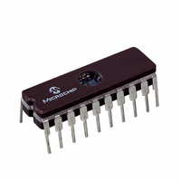
Manufacturer Part Number
PIC16C782/JW
Description
IC MCU EPROM 2KX14 COMP 20CDIP
Manufacturer
Microchip Technology
Series
PIC® 16Cr
Datasheets
1.PIC16C781-ISO.pdf
(186 pages)
2.PIC16C781-ISO.pdf
(8 pages)
3.PIC16C781-ISO.pdf
(8 pages)
Specifications of PIC16C782/JW
Core Processor
PIC
Core Size
8-Bit
Speed
20MHz
Peripherals
Brown-out Detect/Reset, POR, PWM, WDT
Number Of I /o
13
Program Memory Size
3.5KB (2K x 14)
Program Memory Type
EPROM, UV
Ram Size
128 x 8
Voltage - Supply (vcc/vdd)
4 V ~ 5.5 V
Data Converters
A/D 8x8b; D/A 1x8b
Oscillator Type
Internal
Operating Temperature
0°C ~ 70°C
Package / Case
20-CDIP (0.300", 7.62mm) Window
For Use With
DVA16XP202 - ADAPTER DEVICE PIC16C781/782DM163012 - BOARD DEMO PICDEM FOR 16C781/782AC164028 - MODULE SKT PROMATEII 20SOIC/DIP
Lead Free Status / RoHS Status
Contains lead / RoHS non-compliant
Eeprom Size
-
Connectivity
-
Other names
Q1137459
Available stocks
Company
Part Number
Manufacturer
Quantity
Price


14.2
14.2.1
The PIC16C781/782 can be operated in eight different
oscillator modes. The user can program three configu-
ration bits FOSC<2:0> to select one of these eight
modes:
• LP
• XT
• HS
• RC
• INTRC Internal 4 MHz/37 kHz (with and without
• EC
14.2.2
In LP, XT, or HS modes, a crystal or ceramic resonator
is connected to the RA7/OSC1/CLKIN and RA6/OSC2/
CLKOUT/T1CKI
(Figure 14-1). The PIC16C781/782 oscillator design
requires the use of a parallel cut crystal. Use of a series
cut crystal may yield a frequency outside of the crystal
manufacturers’ specifications.
FIGURE 14-1:
2001 Microchip Technology Inc.
Note 1: See Table 14-1 and Table 14-2 for recom-
C1
C2
Oscillator Configurations
(1)
(1)
2: A series resistor (RS) may be required for
3: RF varies with the crystal chosen.
Low Power Crystal
Crystal/Resonator
High Speed Crystal/Resonator
External Resistor and Capacitor (with
External Clock
and without CLKOUT)
LP, XT AND HS MODES
CLKOUT)
OSCILLATOR TYPES
mended values of C1 and C2.
AT strip cut crystals.
RA7/OSC1/
CLKIN
Rs
XTAL
(2)
RA6/OSC2
CLKOUT/
T1CKI
pins
CRYSTAL/CERAMIC
RESONATOR OPERATION
(HS, XT OR LP
OSC CONFIGURATION)
to
R
F (3)
establish
PIC16C781/782
SLEEP
oscillation
To
Internal
Logic
Preliminary
TABLE 14-1:
TABLE 14-2:
14.2.3
In applications where the clock source is external, the
PIC16C781/782 should be programmed to select the
EC (External Clock) mode. In this mode, the RA6/
OSC2/CLKOUT/T1CKI pin is available as an I/O pin.
See Figure 14-2 for illustration. To minimize power sup-
ply current drawn, the EC oscillator input should be
driven by a CMOS level square wave.
XT
HS
These values are for design guidance only.
See Notes 1 and 2 in shaded box.
In this test, all resonators used did not have built-in
capacitors.
LP
XT
HS
These values are for design guidance only.
See Notes 1 and 2 in shaded box.
Osc Type
Mode
Note 1: Since each resonator/crystal has its own
2: Higher capacitance increases the stability
EC MODE
455 kHz
2.0 MHz
4.0 MHz
8.0 MHz
16.0 MHz
32 kHz
200 kHz
200 kHz
1 MHz
4 MHz
4 MHz
8 MHz
20 MHz
characteristics, the user should consult
the resonator/crystal manufacturer for
appropriate values of external compo-
nents.
of oscillator but also increases the
start-up time.
Crystal
Freq
PIC16C781/782
Freq
CERAMIC RESONATORS
CAPACITOR SELECTION FOR
CRYSTAL OSCILLATOR
Ranges Tested:
33 pF
15 pF
47-68 pF
15 pF
15 pF
15 pF
15-33 pF
15-33 pF
Cap. Range
68 - 100 pF
15 - 68 pF
15 - 68 pF
10 - 68 pF
10 - 22 pF
C1
C1
DS41171A-page 119
33 pF
15 pF
47-68 pF
15 pF
15 pF
15 pF
15-33 pF
15-33 pF
Cap. Range
68 - 100 pF
15 - 68 pF
15 - 68 pF
10 - 68 pF
10 - 22 pF
C2
C2
Related parts for PIC16C782/JW
Image
Part Number
Description
Manufacturer
Datasheet
Request
R

Part Number:
Description:
3.5KB Flash, 128B RAM, 18 I/O, CLC, CWG, DDS, 10-bit ADC 20 QFN 4x4mm TUBE
Manufacturer:
Microchip Technology
Datasheet:

Part Number:
Description:
3.5KB Flash, 128B RAM, 18 I/O, CLC, CWG, DDS, 10-bit ADC 20 PDIP .300in TUBE
Manufacturer:
Microchip Technology
Datasheet:

Part Number:
Description:
3.5KB Flash, 128B RAM, 18 I/O, CLC, CWG, DDS, 10-bit ADC 20 SOIC .300in TUBE
Manufacturer:
Microchip Technology
Datasheet:

Part Number:
Description:
3.5KB Flash, 128B RAM, 18 I/O, CLC, CWG, DDS, 10-bit ADC 20 SSOP .209in TUBE
Manufacturer:
Microchip Technology
Datasheet:
Part Number:
Description:
3.5KB Flash, 128B RAM, 18 I/O, CLC, CWG, DDS, 10-bit ADC 20 QFN 4x4mm TUBE
Manufacturer:
Microchip Technology
Datasheet:
Part Number:
Description:
3.5KB Flash, 128B RAM, 18 I/O, CLC, CWG, DDS, 10-bit ADC 20 PDIP .300in TUBE
Manufacturer:
Microchip Technology
Datasheet:
Part Number:
Description:
3.5KB Flash, 128B RAM, 18 I/O, CLC, CWG, DDS, 10-bit ADC 20 SOIC .300in TUBE
Manufacturer:
Microchip Technology
Datasheet:
Part Number:
Description:
3.5KB Flash, 128B RAM, 18 I/O, CLC, CWG, DDS, 10-bit ADC 20 SSOP .209in TUBE
Manufacturer:
Microchip Technology
Datasheet:
Part Number:
Description:
3.5KB Flash, 128B RAM, 18 I/O, CLC, CWG, DDS, 10-bit ADC 20 QFN 4x4mm T/R
Manufacturer:
Microchip Technology
Datasheet:
Part Number:
Description:
3.5KB Flash, 128B RAM, 18 I/O, CLC, CWG, DDS, 10-bit ADC 20 SOIC .300in T/R
Manufacturer:
Microchip Technology
Datasheet:
Part Number:
Description:
3.5KB Flash, 128B RAM, 18 I/O, CLC, CWG, DDS, 10-bit ADC 20 SSOP .209in T/R
Manufacturer:
Microchip Technology
Datasheet:
Part Number:
Description:
3.5KB Flash, 128B RAM, 18 I/O, CLC, CWG, DDS, 10-bit ADC 20 QFN 4x4mm TUBE
Manufacturer:
Microchip Technology
Datasheet:
Part Number:
Description:
3.5KB Flash, 128B RAM, 18 I/O, CLC, CWG, DDS, 10-bit ADC 20 PDIP .300in TUBE
Manufacturer:
Microchip Technology
Datasheet:
Part Number:
Description:
3.5KB Flash, 128B RAM, 18 I/O, CLC, CWG, DDS, 10-bit ADC 20 SOIC .300in TUBE
Manufacturer:
Microchip Technology
Datasheet:
Part Number:
Description:
3.5KB Flash, 128B RAM, 18 I/O, CLC, CWG, DDS, 10-bit ADC 20 SSOP .209in TUBE
Manufacturer:
Microchip Technology
Datasheet: