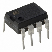
ST7FLITEUS5B6 STMicroelectronics, ST7FLITEUS5B6 Datasheet - Page 45

ST7FLITEUS5B6
Manufacturer Part Number
ST7FLITEUS5B6
Description
MCU 8BIT 1KB FLASH 128KB 8-DIP
Manufacturer
STMicroelectronics
Series
ST7r
Datasheet
1.STEVAL-IFS006V1.pdf
(136 pages)
Specifications of ST7FLITEUS5B6
Core Processor
ST7
Core Size
8-Bit
Speed
8MHz
Peripherals
LVD, POR, PWM, WDT
Number Of I /o
5
Program Memory Size
1KB (1K x 8)
Program Memory Type
FLASH
Ram Size
128 x 8
Voltage - Supply (vcc/vdd)
2.4 V ~ 5.5 V
Data Converters
A/D 5x10b
Oscillator Type
Internal
Operating Temperature
-40°C ~ 85°C
Package / Case
8-DIP (0.300", 7.62mm)
Controller Family/series
ST7
No. Of I/o's
5
Ram Memory Size
128Byte
Cpu Speed
8MHz
No. Of Timers
2
Rohs Compliant
Yes
For Use With
497-6403 - BOARD EVAL 8BIT MICRO + TDE1708497-6407 - BOARD EVAL FOR VACUUM CLEANER497-5861 - EVAL BRD POWER MOSFET/8PIN MCU497-5858 - EVAL BOARD PLAYBACK ST7FLITE497-5515 - EVAL BOARD PHASE CTRL DIMMER497-5049 - KIT STARTER RAISONANCE ST7FLITE497-5046 - KIT TOOL FOR ST7/UPSD/STR7 MCU
Lead Free Status / RoHS Status
Lead free / RoHS Compliant
Eeprom Size
-
Connectivity
-
Other names
497-5636-5
Available stocks
Company
Part Number
Manufacturer
Quantity
Price
Company:
Part Number:
ST7FLITEUS5B6
Manufacturer:
STMicroelectronics
Quantity:
8
ST7LITEUS2, ST7LITEUS5
7.4.2
Note:
Auxiliary voltage detector (AVD)
The voltage detector function (AVD) is based on an analog comparison between a V
and V
reference value for falling voltage is lower than the V
voltage in order to avoid parasitic detection (hysteresis).
The output of the AVD comparator is directly readable by the application software through a
real time status bit (AVDF) in the SICSR register. This bit is read only.
Monitoring the V
The AVD threshold is selected by the AVD[1:0] bits in the AVDTHCR register.
If the AVD interrupt is enabled, an interrupt is generated when the voltage crosses the
V
In the case of a drop in voltage, the AVD interrupt acts as an early warning, allowing
software to shut down safely before the LVD resets the microcontroller. See
The interrupt on the rising edge is used to inform the application that the V
is over
Make sure the right combination of LVD and AVD thresholds is used as LVD and AVD levels
are not correlated. Refer to
Figure 17. Using the AVD to monitor V
AVDF bit
AVD INTERRUPT
REQUEST
IF AVDIE bit = 1
IT+(AVD)
LVD RESET
V
V
V
V
IT+(AVD)
IT+(LVD)
IT-(LVD)
IT-(AVD)
IT+(AVD)
or V
V
DD
IT-(AVD)
reference value and the V
0
DD
threshold (AVDF bit is set).
main supply
1
Table 47 on page 95
INTERRUPT Cleared by
V
Early Warning Interrupt
(Power has dropped, MCU not
not yet in reset)
hyst
reset
RESET
DD
DD
main supply voltage (V
and
IT+(AVD)
Table 48 on page 96
1
reference value for rising
INTERRUPT Cleared by
AVD
hardware
). The V
0
DD
for more details.
Figure
IT-(AVD)
warning state
Interrupts
17.
IT-(AVD)
45/136


