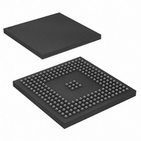
AT91SAM9XE256-CU Atmel, AT91SAM9XE256-CU Datasheet - Page 159

AT91SAM9XE256-CU
Manufacturer Part Number
AT91SAM9XE256-CU
Description
MCU ARM9 256K FLASH 217-BGA
Manufacturer
Atmel
Series
AT91SAMr
Specifications of AT91SAM9XE256-CU
Core Processor
ARM9
Core Size
16/32-Bit
Speed
180MHz
Connectivity
EBI/EMI, Ethernet, I²C, MMC, SPI, SSC, UART/USART, USB
Peripherals
Brown-out Detect/Reset, POR, PWM, WDT
Number Of I /o
96
Program Memory Size
256KB (256K x 8)
Program Memory Type
FLASH
Ram Size
56K x 8
Voltage - Supply (vcc/vdd)
1.65 V ~ 1.95 V
Data Converters
A/D 4x10b
Oscillator Type
Internal
Operating Temperature
-40°C ~ 85°C
Package / Case
217-LFBGA
Processor Series
AT91SAMx
Core
ARM926EJ-S
Data Bus Width
32 bit
Data Ram Size
32 KB
Interface Type
2-Wire, EBI, I2S, SPI, USART
Maximum Clock Frequency
180 MHz
Number Of Programmable I/os
96
Number Of Timers
6
Maximum Operating Temperature
+ 85 C
Mounting Style
SMD/SMT
3rd Party Development Tools
JTRACE-ARM-2M, KSK-AT91SAM9XE-PL, MDK-ARM, RL-ARM, ULINK2
Development Tools By Supplier
AT91SAM-ICE, AT91-ISP, AT91SAM9XE-EK
Minimum Operating Temperature
- 40 C
On-chip Adc
10 bit, 4 Channel
Package
217LFBGA
Device Core
ARM926EJ-S
Family Name
91S
Maximum Speed
180 MHz
Operating Supply Voltage
1.8|2.5|3.3 V
For Use With
AT91SAM9XE-EK - KIT EVAL FOR AT91SAM9XEAT91SAM-ICE - EMULATOR FOR AT91 ARM7/ARM9
Lead Free Status / RoHS Status
Lead free / RoHS Compliant
Eeprom Size
-
Lead Free Status / Rohs Status
Lead free / RoHS Compliant
Available stocks
Company
Part Number
Manufacturer
Quantity
Price
Company:
Part Number:
AT91SAM9XE256-CU
Manufacturer:
ATMEL
Quantity:
215
- Current page: 159 of 860
- Download datasheet (13Mb)
21. AT91SAM9XE Bus Matrix
21.1
21.2
21.3
21.3.1
21.3.2
21.3.3
6254C–ATARM–22-Jan-10
Description
Memory Mapping
Special Bus Granting Techniques
No Default Master
Last Access Master
Fixed Default Master
Bus Matrix implements a multi-layer AHB, based on AHB-Lite protocol, that enables parallel
access paths between multiple AHB masters and slaves in a system, which increases the over-
all bandwidth. Bus Matrix interconnects 6 AHB Masters to 5 AHB Slaves. The normal latency to
connect a master to a slave is one cycle except for the default master of the accessed slave
which is connected directly (zero cycle latency).
The Bus Matrix user interface is compliant with ARM
Chip Configuration User Interface with Registers that allow the Bus Matrix to support application
specific features.
Bus Matrix provides one decoder for every AHB Master Interface. The decoder offers each AHB
Master several memory mappings. In fact, depending on the product, each memory area may be
assigned to several slaves. Booting at the same address while using different AHB slaves (i.e.,
external RAM, internal ROM or internal Flash, etc.) becomes possible.
The Bus Matrix user interface provides Master Remap Control Register (MATRIX_MRCR) that
allows to perform remap action for every master independently.
The Bus Matrix provides some speculative bus granting techniques in order to anticipate access
requests from some masters. This mechanism allows to reduce latency at first accesses of a
burst or single transfer. The bus granting mechanism allows to set a default master for every
slave.
At the end of the current access, if no other request is pending, the slave remains connected to
its associated default master. A slave can be associated with three kinds of default masters: no
default master, last access master and fixed default master.
At the end of the current access, if no other request is pending, the slave is disconnected from
all masters. No Default Master suits low power mode.
At the end of the current access, if no other request is pending, the slave remains connected to
the last master that performed an access request.
At the end of the current access, if no other request is pending, the slave connects to itsfixed
default master. Unlike last access master, the fixed master doesn’t change unless the user mod-
ifies it by a software action (field FIXED_DEFMSTR of the related MATRIX_SCFG).
To change from one kind of default master to another, the Bus Matrix user interface provides the
Slave Configuration Registers, one for each slave, that allow to set a default master for each
slave. The Slave Configuration Register contains two fields:
DEFMSTR_TYPE and FIXED_DEFMSTR. The 2-bit DEFMSTR_TYPE field allows to choose
the default master type (no default, last access master, fixed default master) whereas the 4-bit
AT91SAM9XE128/256/512 Preliminary
®
Advance Peripheral Bus and provides a
159
Related parts for AT91SAM9XE256-CU
Image
Part Number
Description
Manufacturer
Datasheet
Request
R

Part Number:
Description:
KIT EVAL FOR AT91SAM9XE
Manufacturer:
Atmel
Datasheet:

Part Number:
Description:
MCU ARM9 64K SRAM 144-LFBGA
Manufacturer:
Atmel
Datasheet:

Part Number:
Description:
IC ARM7 MCU FLASH 256K 100LQFP
Manufacturer:
Atmel
Datasheet:

Part Number:
Description:
IC ARM9 MPU 217-LFBGA
Manufacturer:
Atmel
Datasheet:

Part Number:
Description:
MCU ARM9 ULTRA LOW PWR 217-LFBGA
Manufacturer:
Atmel
Datasheet:

Part Number:
Description:
MCU ARM9 324-TFBGA
Manufacturer:
Atmel
Datasheet:

Part Number:
Description:
IC MCU ARM9 SAMPLING 217CBGA
Manufacturer:
Atmel
Datasheet:

Part Number:
Description:
IC ARM9 MCU 217-LFBGA
Manufacturer:
Atmel
Datasheet:

Part Number:
Description:
IC ARM9 MCU 208-PQFP
Manufacturer:
Atmel
Datasheet:

Part Number:
Description:
MCU ARM 512K HS FLASH 100-LQFP
Manufacturer:
Atmel
Datasheet:

Part Number:
Description:
MCU ARM 512K HS FLASH 100-TFBGA
Manufacturer:
Atmel
Datasheet:

Part Number:
Description:
IC ARM9 MCU 200 MHZ 324-TFBGA
Manufacturer:
Atmel
Datasheet:

Part Number:
Description:
IC ARM MCU 16BIT 128K 256BGA
Manufacturer:
Atmel
Datasheet:

Part Number:
Description:
IC ARM7 MCU 32BIT 128K 64LQFP
Manufacturer:
Atmel
Datasheet:

Part Number:
Description:
IC ARM7 MCU FLASH 256K 128-LQFP
Manufacturer:
Atmel
Datasheet:


