ATSAM3S4AA-MU Atmel, ATSAM3S4AA-MU Datasheet - Page 927
ATSAM3S4AA-MU
Manufacturer Part Number
ATSAM3S4AA-MU
Description
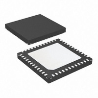
IC MCU 32BIT 256KB FLASH 48QFN
Manufacturer
Atmel
Series
SAM3Sr
Specifications of ATSAM3S4AA-MU
Core Processor
ARM® Cortex-M3™
Core Size
32-Bit
Speed
64MHz
Connectivity
I²C, MMC, SPI, SSC, UART/USART, USB
Peripherals
Brown-out Detect/Reset, DMA, I²S, POR, PWM, WDT
Number Of I /o
34
Program Memory Size
256KB (256K x 8)
Program Memory Type
FLASH
Ram Size
48K x 8
Voltage - Supply (vcc/vdd)
1.62 V ~ 1.95 V
Data Converters
A/D 8x10/12b
Oscillator Type
Internal
Operating Temperature
-40°C ~ 85°C
Package / Case
48-VQFN Exposed Pad, 48-HVQFN, 48-SQFN, 48-DHVQFN
Processor Series
ATSAM3x
Core
ARM Cortex M3
3rd Party Development Tools
JTRACE-CM3, MDK-ARM, RL-ARM, ULINK2
Development Tools By Supplier
ATSAM3S-EK
Lead Free Status / RoHS Status
Lead free / RoHS Compliant
Eeprom Size
-
Lead Free Status / Rohs Status
Details
Available stocks
Company
Part Number
Manufacturer
Quantity
Price

Part Number:
ATSAM3S4AA-MU
Manufacturer:
MICROCHIP/微芯
Quantity:
20 000


37.4
37.4.1
37.4.2
37.4.3
6500C–ATARM–8-Feb-11
Product Dependencies
I/O Lines
Power Management
Interrupt
For further details on the USB Device hardware implementation, see the specific Product Prop-
erties document.
The USB physical transceiver is integrated into the product. The bidirectional differential signals
DDP and DDM are available from the product boundary.
One I/O line may be used by the application to check that VBUS is still available from the host.
Self-powered devices may use this entry to be notified that the host has been powered off. In
this case, the pull-up on DP must be disabled in order to prevent feeding current to the host. The
application should disconnect the transceiver, then remove the pull-up.
The USB pins are shared with PIO lines. By default, the USB function is activated, and pins DDP
and DDM are used for USB. To configure DDP or DDM as PIOs, the user needs to configure the
system I/O configuration register (CCFG_SYSIO) in the MATRIX.
The USB device peripheral requires a 48 MHz clock. This clock must be generated by a PLL
with an accuracy of ± 0.25%.
Thus, the USB device receives two clocks from the Power Management Controller (PMC): the
master clock, MCK, used to drive the peripheral user interface, and the UDPCK, used to inter-
face with the bus USB signals (recovered 12 MHz domain).
WARNING: The UDP peripheral clock in the Power Management Controller (PMC) must be
enabled before any read/write operations to the UDP registers including the UDP_TXVC
register.
The USB device interface has an interrupt line connected to the Interrupt Controller.
Handling the USB device interrupt requires programming the Interrupt Controller before
configuring the UDP.
Table 37-3.
Instance
UDP
Peripheral IDs
34
ID
SAM3S Preliminary
927
Related parts for ATSAM3S4AA-MU
Image
Part Number
Description
Manufacturer
Datasheet
Request
R

Part Number:
Description:
KIT EVAL FOR ATSAM3S4C
Manufacturer:
Atmel
Datasheet:
Part Number:
Description:
Development Boards & Kits - ARM EVAL KIT SAM3S8 & SAM3SD8 series
Manufacturer:
Atmel
Datasheet:

Part Number:
Description:
AT91 ARM Cortex M3-based Processor
Manufacturer:
ATMEL [ATMEL Corporation]
Datasheet:

Part Number:
Description:
DEV KIT FOR AVR/AVR32
Manufacturer:
Atmel
Datasheet:

Part Number:
Description:
INTERVAL AND WIPE/WASH WIPER CONTROL IC WITH DELAY
Manufacturer:
ATMEL Corporation
Datasheet:
Part Number:
Description:
Low-Voltage Voice-Switched IC for Hands-Free Operation
Manufacturer:
ATMEL Corporation
Datasheet:
Part Number:
Description:
MONOLITHIC INTEGRATED FEATUREPHONE CIRCUIT
Manufacturer:
ATMEL Corporation
Datasheet:
Part Number:
Description:
AM-FM Receiver IC U4255BM-M
Manufacturer:
ATMEL Corporation
Datasheet:
Part Number:
Description:
Monolithic Integrated Feature Phone Circuit
Manufacturer:
ATMEL Corporation
Datasheet:
Part Number:
Description:
Multistandard Video-IF and Quasi Parallel Sound Processing
Manufacturer:
ATMEL Corporation
Datasheet:
Part Number:
Description:
High-performance EE PLD
Manufacturer:
ATMEL Corporation
Datasheet:
Part Number:
Description:
8-bit Flash Microcontroller
Manufacturer:
ATMEL Corporation
Datasheet: