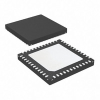
ATSAM3S4AA-MU Atmel, ATSAM3S4AA-MU Datasheet - Page 219

ATSAM3S4AA-MU
Manufacturer Part Number
ATSAM3S4AA-MU
Description
IC MCU 32BIT 256KB FLASH 48QFN
Manufacturer
Atmel
Series
SAM3Sr
Specifications of ATSAM3S4AA-MU
Core Processor
ARM® Cortex-M3™
Core Size
32-Bit
Speed
64MHz
Connectivity
I²C, MMC, SPI, SSC, UART/USART, USB
Peripherals
Brown-out Detect/Reset, DMA, I²S, POR, PWM, WDT
Number Of I /o
34
Program Memory Size
256KB (256K x 8)
Program Memory Type
FLASH
Ram Size
48K x 8
Voltage - Supply (vcc/vdd)
1.62 V ~ 1.95 V
Data Converters
A/D 8x10/12b
Oscillator Type
Internal
Operating Temperature
-40°C ~ 85°C
Package / Case
48-VQFN Exposed Pad, 48-HVQFN, 48-SQFN, 48-DHVQFN
Processor Series
ATSAM3x
Core
ARM Cortex M3
3rd Party Development Tools
JTRACE-CM3, MDK-ARM, RL-ARM, ULINK2
Development Tools By Supplier
ATSAM3S-EK
Lead Free Status / RoHS Status
Lead free / RoHS Compliant
Eeprom Size
-
Lead Free Status / Rohs Status
Details
Available stocks
Company
Part Number
Manufacturer
Quantity
Price
Part Number:
ATSAM3S4AA-MU
Manufacturer:
MICROCHIP/微芯
Quantity:
20 000
- Current page: 219 of 1118
- Download datasheet (24Mb)
11.5.3.1
11.5.4
11.5.5
6500C–ATARM–8-Feb-11
FPB (Flash Patch Breakpoint)
DWT (Data Watchpoint and Trace)
SW-DP and JTAG-DP Selection Mechanism
When the Serial Wire Debug Port is active, TDO/TRACESWO can be used for trace. The asyn-
chronous TRACE output (TRACESWO) is multiplexed with TDO. So the asynchronous trace
can only be used with SW-DP, not JTAG-DP.
Table 11-2.
SW-DP or JTAG-DP mode is selected when JTAGSEL is low. It is not possible to switch directly
between SWJ-DP and JTAG boundary scan operations. A chip reset must be performed after
JTAGSEL is changed.
Debug port selection mechanism is done by sending specific SWDIOTMS sequence. The JTAG-
DP is selected by default after reset.
The FPB:
The FPB unit contains:
The DWT contains four comparators which can be configured to generate the following:
Pin Name
TMS/SWDIO
TCK/SWCLK
TDI
TDO/TRACESWO
• Switch from JTAG-DP to SW-DP. The sequence is:
• Switch from SWD to JTAG. The sequence is:
• Implements hardware breakpoints
• Patches code and data from code space to system space.
• Two literal comparators for matching against literal loads from Code space, and remapping to
• Six instruction comparators for matching against instruction fetches from Code space and
• Alternatively, comparators can also be configured to generate a Breakpoint instruction to the
• PC sampling packets at set intervals
• PC or Data watchpoint packets
a corresponding area in System space.
remapping to a corresponding area in System space.
processor core on a match.
– Send more than 50 SWCLKTCK cycles with SWDIOTMS = 1
– Send the 16-bit sequence on SWDIOTMS = 0111100111100111 (0x79E7 MSB first)
– Send more than 50 SWCLKTCK cycles with SWDIOTMS = 1
– Send more than 50 SWCLKTCK cycles with SWDIOTMS = 1
– Send the 16-bit sequence on SWDIOTMS = 0011110011100111 (0x3CE7 MSB first)
– Send more than 50 SWCLKTCK cycles with SWDIOTMS = 1
SWJ-DP Pin List
JTAG Port
TMS
TDO
TCK
TDI
SAM3S Preliminary
TRACESWO (optional: trace)
Serial Wire Debug Port
SWCLK
SWDIO
-
219
Related parts for ATSAM3S4AA-MU
Image
Part Number
Description
Manufacturer
Datasheet
Request
R

Part Number:
Description:
KIT EVAL FOR ATSAM3S4C
Manufacturer:
Atmel
Datasheet:

Part Number:
Description:
Development Boards & Kits - ARM EVAL KIT SAM3S8 & SAM3SD8 series
Manufacturer:
Atmel
Datasheet:

Part Number:
Description:
AT91 ARM Cortex M3-based Processor
Manufacturer:
ATMEL [ATMEL Corporation]
Datasheet:

Part Number:
Description:
DEV KIT FOR AVR/AVR32
Manufacturer:
Atmel
Datasheet:

Part Number:
Description:
INTERVAL AND WIPE/WASH WIPER CONTROL IC WITH DELAY
Manufacturer:
ATMEL Corporation
Datasheet:

Part Number:
Description:
Low-Voltage Voice-Switched IC for Hands-Free Operation
Manufacturer:
ATMEL Corporation
Datasheet:

Part Number:
Description:
MONOLITHIC INTEGRATED FEATUREPHONE CIRCUIT
Manufacturer:
ATMEL Corporation
Datasheet:

Part Number:
Description:
AM-FM Receiver IC U4255BM-M
Manufacturer:
ATMEL Corporation
Datasheet:

Part Number:
Description:
Monolithic Integrated Feature Phone Circuit
Manufacturer:
ATMEL Corporation
Datasheet:

Part Number:
Description:
Multistandard Video-IF and Quasi Parallel Sound Processing
Manufacturer:
ATMEL Corporation
Datasheet:

Part Number:
Description:
High-performance EE PLD
Manufacturer:
ATMEL Corporation
Datasheet:

Part Number:
Description:
8-bit Flash Microcontroller
Manufacturer:
ATMEL Corporation
Datasheet:


