ATSAM3S4AA-MU Atmel, ATSAM3S4AA-MU Datasheet - Page 743
ATSAM3S4AA-MU
Manufacturer Part Number
ATSAM3S4AA-MU
Description
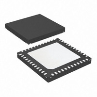
IC MCU 32BIT 256KB FLASH 48QFN
Manufacturer
Atmel
Series
SAM3Sr
Specifications of ATSAM3S4AA-MU
Core Processor
ARM® Cortex-M3™
Core Size
32-Bit
Speed
64MHz
Connectivity
I²C, MMC, SPI, SSC, UART/USART, USB
Peripherals
Brown-out Detect/Reset, DMA, I²S, POR, PWM, WDT
Number Of I /o
34
Program Memory Size
256KB (256K x 8)
Program Memory Type
FLASH
Ram Size
48K x 8
Voltage - Supply (vcc/vdd)
1.62 V ~ 1.95 V
Data Converters
A/D 8x10/12b
Oscillator Type
Internal
Operating Temperature
-40°C ~ 85°C
Package / Case
48-VQFN Exposed Pad, 48-HVQFN, 48-SQFN, 48-DHVQFN
Processor Series
ATSAM3x
Core
ARM Cortex M3
3rd Party Development Tools
JTRACE-CM3, MDK-ARM, RL-ARM, ULINK2
Development Tools By Supplier
ATSAM3S-EK
Lead Free Status / RoHS Status
Lead free / RoHS Compliant
Eeprom Size
-
Lead Free Status / Rohs Status
Details
Available stocks
Company
Part Number
Manufacturer
Quantity
Price

Part Number:
ATSAM3S4AA-MU
Manufacturer:
MICROCHIP/微芯
Quantity:
20 000


34. Timer Counter (TC)
34.1
6500C–ATARM–8-Feb-11
Description
The Timer Counter (TC) includes three identical 16-bit Timer Counter channels.
Each channel can be independently programmed to perform a wide range of functions including
frequency measurement, event counting, interval measurement, pulse generation, delay timing
and pulse width modulation.
Each channel has three external clock inputs, five internal clock inputs and two multi-purpose
input/output signals which can be configured by the user. Each channel drives an internal inter-
rupt signal which can be programmed to generate processor interrupts.
The Timer Counter (TC) embeds a quadrature decoder logic connected in front of the 3 timers
and driven by TIOA0, TIOB0 and TIOA1 inputs. When enabled, the quadrature decoder per-
forms the input lines filtering, decoding of quadrature signals and connects to the 3
timers/counters in order to read the position and speed of the motor through user interface.
The Timer Counter block has two global registers which act upon all three TC channels.
The Block Control Register allows the three channels to be started simultaneously with the same
instruction.
The Block Mode Register defines the external clock inputs for each channel, allowing them to be
chained.
Table 34-1
Counter 0 to 2.
Table 34-1.
Note:
Name
TIMER_CLOCK1
TIMER_CLOCK2
TIMER_CLOCK3
TIMER_CLOCK4
TIMER_CLOCK5
1. When Slow Clock is selected for Master Clock (CSS = 0 in PMC Master CLock Register),
TIMER_CLOCK5 input is Master Clock, i.e., Slow CLock modified by PRES and MDIV fields.
gives the assignment of the device Timer Counter clock inputs common to Timer
Timer Counter Clock Assignment
(1)
Definition
MCK/2
MCK/8
MCK/32
MCK/128
SLCK
SAM3S Preliminary
743
Related parts for ATSAM3S4AA-MU
Image
Part Number
Description
Manufacturer
Datasheet
Request
R

Part Number:
Description:
KIT EVAL FOR ATSAM3S4C
Manufacturer:
Atmel
Datasheet:
Part Number:
Description:
Development Boards & Kits - ARM EVAL KIT SAM3S8 & SAM3SD8 series
Manufacturer:
Atmel
Datasheet:

Part Number:
Description:
AT91 ARM Cortex M3-based Processor
Manufacturer:
ATMEL [ATMEL Corporation]
Datasheet:

Part Number:
Description:
DEV KIT FOR AVR/AVR32
Manufacturer:
Atmel
Datasheet:

Part Number:
Description:
INTERVAL AND WIPE/WASH WIPER CONTROL IC WITH DELAY
Manufacturer:
ATMEL Corporation
Datasheet:
Part Number:
Description:
Low-Voltage Voice-Switched IC for Hands-Free Operation
Manufacturer:
ATMEL Corporation
Datasheet:
Part Number:
Description:
MONOLITHIC INTEGRATED FEATUREPHONE CIRCUIT
Manufacturer:
ATMEL Corporation
Datasheet:
Part Number:
Description:
AM-FM Receiver IC U4255BM-M
Manufacturer:
ATMEL Corporation
Datasheet:
Part Number:
Description:
Monolithic Integrated Feature Phone Circuit
Manufacturer:
ATMEL Corporation
Datasheet:
Part Number:
Description:
Multistandard Video-IF and Quasi Parallel Sound Processing
Manufacturer:
ATMEL Corporation
Datasheet:
Part Number:
Description:
High-performance EE PLD
Manufacturer:
ATMEL Corporation
Datasheet:
Part Number:
Description:
8-bit Flash Microcontroller
Manufacturer:
ATMEL Corporation
Datasheet: