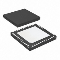
ATSAM3S4AA-MU Atmel, ATSAM3S4AA-MU Datasheet - Page 1104

ATSAM3S4AA-MU
Manufacturer Part Number
ATSAM3S4AA-MU
Description
IC MCU 32BIT 256KB FLASH 48QFN
Manufacturer
Atmel
Series
SAM3Sr
Specifications of ATSAM3S4AA-MU
Core Processor
ARM® Cortex-M3™
Core Size
32-Bit
Speed
64MHz
Connectivity
I²C, MMC, SPI, SSC, UART/USART, USB
Peripherals
Brown-out Detect/Reset, DMA, I²S, POR, PWM, WDT
Number Of I /o
34
Program Memory Size
256KB (256K x 8)
Program Memory Type
FLASH
Ram Size
48K x 8
Voltage - Supply (vcc/vdd)
1.62 V ~ 1.95 V
Data Converters
A/D 8x10/12b
Oscillator Type
Internal
Operating Temperature
-40°C ~ 85°C
Package / Case
48-VQFN Exposed Pad, 48-HVQFN, 48-SQFN, 48-DHVQFN
Processor Series
ATSAM3x
Core
ARM Cortex M3
3rd Party Development Tools
JTRACE-CM3, MDK-ARM, RL-ARM, ULINK2
Development Tools By Supplier
ATSAM3S-EK
Lead Free Status / RoHS Status
Lead free / RoHS Compliant
Eeprom Size
-
Lead Free Status / Rohs Status
Details
Available stocks
Company
Part Number
Manufacturer
Quantity
Price
Part Number:
ATSAM3S4AA-MU
Manufacturer:
MICROCHIP/微芯
Quantity:
20 000
- Current page: 1104 of 1118
- Download datasheet (24Mb)
1104
Doc. Rev.
6500B
SAM3S Preliminary
Comments
Electrical Characteristics:
Table 41-2, “DC Characteristics”
Table 41-17, “4/8/12 MHz RC Oscillators
Table 41-7, “DC Flash
Table 41-21, “3 to 20 MHz Crystal Oscillator
Section 41.11 “AC
Table 41-45, “SPI
Table 41-46, “SSC
Table 41-47, “SMC Read Signals - NRD Controlled (READ_MODE =
Table 41-48, “SMC Read Signals - NCS Controlled (READ_MODE=
Table 41-49, “SMC Write Signals - NWE Controlled (WRITE_MODE =
Table 41-50, “SMC Write NCS Controlled (WRITE_MODE =
Table 41-51, “USART SPI
Table 41-53, “Embedded Flash Wait State VDDCORE set at
Table 41-54, “Embedded Flash Wait State VDDCORE set at 1.80V”
Section 41.11.3.1 “Maximum SPI
“Master Read Mode”
“Slave Write Mode”
Section 41.11.7 “USART in SPI Mode
Figure
Table 41-28, “Analog Power Supply
Table 41-29, “Channel Conversion Time and ADC
Table 41-30, “External Voltage Reference
Table 41-35, “Analog
Section 41.7.0.1 “Track and Hold Time versus Source Output
Figure
Table 41-51, “USART SPI
Errata:
Section 44. “SAM3S Series
41-28,
41-30, SPI
Figure
14
Timings”,
Characteristics”, updated the following tables
Timings”,
...2x(SPI
and SPI
41-28, updated with text on line drives.
...F
Inputs”, Input Capacitance, Max value updated.
Characteristics”, 1st cell , I
SPCK
Timings”,
Timings”, all references to SPCK changed to SCK. Min values updated.
15
Errata”, added to the datasheet.
6max
Max = 33 MHz...
repositioned in respect to SCK rising and falling.
(orSPI
V
Frequency”, the following changes:
OH
Characteristics”, updated I
/V
Timings”, all figures, tables and titles renamed USART from UART.
OL
9max
Characteristics”, updated.
Min/Max values swapped.
Input”, removed ADVREF Settling Time.
) ......F
Characteristics”, C
SB
SPCK
Clock”, f
deleted.
Max = 25 MHz...
ADC
0)”,
1.65V”,
, t
Impedance”, replaced text below figure.
VDDANA
LEXT
CP_ADC ,
line modified.
0)”,
1)”,
line.
1)”,
t
START-UP
lines updated & added t
6500C–ATARM–8-Feb-11
SETTLING
Change
Request
Ref.
7208
rfo
rfo
rfo
7225
rfo
rfo
7320
7207/7316
Related parts for ATSAM3S4AA-MU
Image
Part Number
Description
Manufacturer
Datasheet
Request
R

Part Number:
Description:
KIT EVAL FOR ATSAM3S4C
Manufacturer:
Atmel
Datasheet:

Part Number:
Description:
Development Boards & Kits - ARM EVAL KIT SAM3S8 & SAM3SD8 series
Manufacturer:
Atmel
Datasheet:

Part Number:
Description:
AT91 ARM Cortex M3-based Processor
Manufacturer:
ATMEL [ATMEL Corporation]
Datasheet:

Part Number:
Description:
DEV KIT FOR AVR/AVR32
Manufacturer:
Atmel
Datasheet:

Part Number:
Description:
INTERVAL AND WIPE/WASH WIPER CONTROL IC WITH DELAY
Manufacturer:
ATMEL Corporation
Datasheet:

Part Number:
Description:
Low-Voltage Voice-Switched IC for Hands-Free Operation
Manufacturer:
ATMEL Corporation
Datasheet:

Part Number:
Description:
MONOLITHIC INTEGRATED FEATUREPHONE CIRCUIT
Manufacturer:
ATMEL Corporation
Datasheet:

Part Number:
Description:
AM-FM Receiver IC U4255BM-M
Manufacturer:
ATMEL Corporation
Datasheet:

Part Number:
Description:
Monolithic Integrated Feature Phone Circuit
Manufacturer:
ATMEL Corporation
Datasheet:

Part Number:
Description:
Multistandard Video-IF and Quasi Parallel Sound Processing
Manufacturer:
ATMEL Corporation
Datasheet:

Part Number:
Description:
High-performance EE PLD
Manufacturer:
ATMEL Corporation
Datasheet:

Part Number:
Description:
8-bit Flash Microcontroller
Manufacturer:
ATMEL Corporation
Datasheet:


