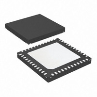
ATSAM3S4AA-MU Atmel, ATSAM3S4AA-MU Datasheet - Page 347

ATSAM3S4AA-MU
Manufacturer Part Number
ATSAM3S4AA-MU
Description
IC MCU 32BIT 256KB FLASH 48QFN
Manufacturer
Atmel
Series
SAM3Sr
Specifications of ATSAM3S4AA-MU
Core Processor
ARM® Cortex-M3™
Core Size
32-Bit
Speed
64MHz
Connectivity
I²C, MMC, SPI, SSC, UART/USART, USB
Peripherals
Brown-out Detect/Reset, DMA, I²S, POR, PWM, WDT
Number Of I /o
34
Program Memory Size
256KB (256K x 8)
Program Memory Type
FLASH
Ram Size
48K x 8
Voltage - Supply (vcc/vdd)
1.62 V ~ 1.95 V
Data Converters
A/D 8x10/12b
Oscillator Type
Internal
Operating Temperature
-40°C ~ 85°C
Package / Case
48-VQFN Exposed Pad, 48-HVQFN, 48-SQFN, 48-DHVQFN
Processor Series
ATSAM3x
Core
ARM Cortex M3
3rd Party Development Tools
JTRACE-CM3, MDK-ARM, RL-ARM, ULINK2
Development Tools By Supplier
ATSAM3S-EK
Lead Free Status / RoHS Status
Lead free / RoHS Compliant
Eeprom Size
-
Lead Free Status / Rohs Status
Details
Available stocks
Company
Part Number
Manufacturer
Quantity
Price
Part Number:
ATSAM3S4AA-MU
Manufacturer:
MICROCHIP/微芯
Quantity:
20 000
- Current page: 347 of 1118
- Download datasheet (24Mb)
22. Bus Matrix (MATRIX)
22.1
22.2
22.2.1
22.2.2
6500C–ATARM–8-Feb-11
Description
Embedded Characteristics
Matrix Masters
Matrix Slaves
The Bus Matrix implements a multi-layer AHB that enables parallel access paths between multi-
ple AHB masters and slaves in a system, which increases the overall bandwidth. Bus Matrix
interconnects 4 AHB Masters to 5 AHB Slaves. The normal latency to connect a master to a
slave is one cycle except for the default master of the accessed slave which is connected
directly (zero cycle latency).
The Bus Matrix user interface also provides a Chip Configuration User Interface with Registers
that allow to support application specific features.
The Bus Matrix of the SAM3S product manages 4 masters, which means that each master can
perform an access concurrently with others, to an available slave.
Each master has its own decoder, which is defined specifically for each master. In order to sim-
plify the addressing, all the masters have the same decodings.
Table 22-1.
The Bus Matrix of the SAM3S product manages 5 slaves. Each slave has its own arbiter, allow-
ing a different arbitration per slave.
Table 22-2.
Master 0
Master 1
Master 2
Master 3
Slave 0
Slave 1
Slave 2
Slave 3
Slave 4
List of Bus Matrix Masters
List of Bus Matrix Slaves
Internal SRAM
Internal ROM
Internal Flash
External Bus Interface
Peripheral Bridge
Cortex-M3 Instruction/Data
Cortex-M3 System
Peripheral DMA Controller (PDC)
CRC Calculation Unit
SAM3S Preliminary
347
Related parts for ATSAM3S4AA-MU
Image
Part Number
Description
Manufacturer
Datasheet
Request
R

Part Number:
Description:
KIT EVAL FOR ATSAM3S4C
Manufacturer:
Atmel
Datasheet:

Part Number:
Description:
Development Boards & Kits - ARM EVAL KIT SAM3S8 & SAM3SD8 series
Manufacturer:
Atmel
Datasheet:

Part Number:
Description:
AT91 ARM Cortex M3-based Processor
Manufacturer:
ATMEL [ATMEL Corporation]
Datasheet:

Part Number:
Description:
DEV KIT FOR AVR/AVR32
Manufacturer:
Atmel
Datasheet:

Part Number:
Description:
INTERVAL AND WIPE/WASH WIPER CONTROL IC WITH DELAY
Manufacturer:
ATMEL Corporation
Datasheet:

Part Number:
Description:
Low-Voltage Voice-Switched IC for Hands-Free Operation
Manufacturer:
ATMEL Corporation
Datasheet:

Part Number:
Description:
MONOLITHIC INTEGRATED FEATUREPHONE CIRCUIT
Manufacturer:
ATMEL Corporation
Datasheet:

Part Number:
Description:
AM-FM Receiver IC U4255BM-M
Manufacturer:
ATMEL Corporation
Datasheet:

Part Number:
Description:
Monolithic Integrated Feature Phone Circuit
Manufacturer:
ATMEL Corporation
Datasheet:

Part Number:
Description:
Multistandard Video-IF and Quasi Parallel Sound Processing
Manufacturer:
ATMEL Corporation
Datasheet:

Part Number:
Description:
High-performance EE PLD
Manufacturer:
ATMEL Corporation
Datasheet:

Part Number:
Description:
8-bit Flash Microcontroller
Manufacturer:
ATMEL Corporation
Datasheet:


