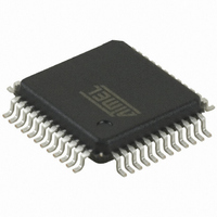
AT32UC3B1256-AUR Atmel, AT32UC3B1256-AUR Datasheet - Page 486

AT32UC3B1256-AUR
Manufacturer Part Number
AT32UC3B1256-AUR
Description
MCU AVR32 256K FLASH 48-TQFP
Manufacturer
Atmel
Series
AVR®32 UC3r
Datasheet
1.AT32UC3B164-AUR.pdf
(680 pages)
Specifications of AT32UC3B1256-AUR
Package / Case
48-TQFP, 48-VQFP
Voltage - Supply (vcc/vdd)
1.65 V ~ 1.95 V
Operating Temperature
-40°C ~ 85°C
Speed
60MHz
Number Of I /o
28
Core Processor
AVR
Program Memory Type
FLASH
Ram Size
32K x 8
Program Memory Size
256KB (256K x 8)
Data Converters
A/D 6x10b
Oscillator Type
Internal
Peripherals
Brown-out Detect/Reset, DMA, POR, PWM, WDT
Connectivity
I²C, IrDA, SPI, SSC, UART/USART, USB
Core Size
32-Bit
Lead Free Status / RoHS Status
Lead free / RoHS Compliant
Eeprom Size
-
Available stocks
Company
Part Number
Manufacturer
Quantity
Price
Company:
Part Number:
AT32UC3B1256-AUR
Manufacturer:
OMRON
Quantity:
12 000
- Current page: 486 of 680
- Download datasheet (10Mb)
23.5.2
23.5.3
23.5.4
23.5.5
23.6
23.6.1
23.6.1.1
23.6.1.2
32059J–12/2010
Functional Description
Power Management
Clocks
Interrupts
Debug Operation
TC Description
Channel I/O Signals
16-bit counter
If the CPU enters a sleep mode that disables clocks used by the TC, the TC will stop functioning
and resume operation after the system wakes up from sleep mode.
The clock for the TC bus interface (CLK_TC) is generated by the Power Manager. This clock is
enabled at reset, and can be disabled in the Power Manager. It is recommended to disable the
TC before disabling the clock, to avoid freezing the TC in an undefined state.
The TC interrupt request line is connected to the interrupt controller. Using the TC interrupt
requires the interrupt controller to be programmed first.
The Timer Counter clocks are frozen during debug operation, unless the OCD system keeps
peripherals running in debug operation.
The three channels of the Timer Counter are independent and identical in operation. The regis-
ters for channel programming are listed in
As described in
Table 23-2.
Each channel is organized around a 16-bit counter. The value of the counter is incremented at
each positive edge of the selected clock. When the counter has reached the value 0xFFFF and
passes to 0x0000, an overflow occurs and the Counter Overflow Status bit in the Channel n Sta-
tus Register (SRn.COVFS) is set.
The current value of the counter is accessible in real time by reading the Channel n Counter
Value Register (CVn). The counter can be reset by a trigger. In this case, the counter value
passes to 0x0000 on the next valid edge of the selected clock.
Block/Channel
Channel Signal
Channel I/O Signals Description
Figure 23-1 on page
XC0, XC1, XC2
Signal Name
SYNC
TIOA
TIOB
INT
485, each Channel has the following I/O signals.
Figure 23-3 on page
Description
External Clock Inputs
Capture mode: Timer Counter Input
Waveform mode: Timer Counter Output
Capture mode: Timer Counter Input
Waveform mode: Timer Counter Input/Output
Interrupt Signal Output
Synchronization Input Signal
501.
AT32UC3B
486
Related parts for AT32UC3B1256-AUR
Image
Part Number
Description
Manufacturer
Datasheet
Request
R

Part Number:
Description:
DEV KIT FOR AVR/AVR32
Manufacturer:
Atmel
Datasheet:

Part Number:
Description:
INTERVAL AND WIPE/WASH WIPER CONTROL IC WITH DELAY
Manufacturer:
ATMEL Corporation
Datasheet:

Part Number:
Description:
Low-Voltage Voice-Switched IC for Hands-Free Operation
Manufacturer:
ATMEL Corporation
Datasheet:

Part Number:
Description:
MONOLITHIC INTEGRATED FEATUREPHONE CIRCUIT
Manufacturer:
ATMEL Corporation
Datasheet:

Part Number:
Description:
AM-FM Receiver IC U4255BM-M
Manufacturer:
ATMEL Corporation
Datasheet:

Part Number:
Description:
Monolithic Integrated Feature Phone Circuit
Manufacturer:
ATMEL Corporation
Datasheet:

Part Number:
Description:
Multistandard Video-IF and Quasi Parallel Sound Processing
Manufacturer:
ATMEL Corporation
Datasheet:

Part Number:
Description:
High-performance EE PLD
Manufacturer:
ATMEL Corporation
Datasheet:

Part Number:
Description:
8-bit Flash Microcontroller
Manufacturer:
ATMEL Corporation
Datasheet:

Part Number:
Description:
2-Wire Serial EEPROM
Manufacturer:
ATMEL Corporation
Datasheet:


