DEMO9S08EL32 Freescale Semiconductor, DEMO9S08EL32 Datasheet - Page 295
DEMO9S08EL32
Manufacturer Part Number
DEMO9S08EL32
Description
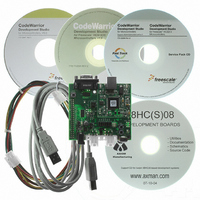
BOARD DEMO FOR 9S08 EL MCU
Manufacturer
Freescale Semiconductor
Type
MCUr
Datasheets
1.DEMO9S08EL32.pdf
(356 pages)
2.DEMO9S08EL32.pdf
(14 pages)
3.DEMO9S08EL32.pdf
(2 pages)
Specifications of DEMO9S08EL32
Contents
Evaluation Board
Processor To Be Evaluated
MC9S08EL32
Data Bus Width
8 bit
Interface Type
RS-232, USB
Operating Supply Voltage
12 V
Silicon Manufacturer
Freescale
Core Architecture
HCS08
Core Sub-architecture
HCS08
Silicon Core Number
MC9S08
Silicon Family Name
S08EL
Rohs Compliant
Yes
For Use With/related Products
MC9S08EL32
Lead Free Status / RoHS Status
Lead free / RoHS Compliant


16.4.1.3
The main timer counter has two counting modes. When center-aligned PWM is selected (CPWMS=1), the
counter operates in up/down counting mode. Otherwise, the counter operates as a simple up counter. As
an up counter, the timer counter counts from 0x0000 through its terminal count and then continues with
0x0000. The terminal count is 0xFFFF or a modulus value in TPMxMODH:TPMxMODL.
When center-aligned PWM operation is specified, the counter counts up from 0x0000 through its terminal
count and then down to 0x0000 where it changes back to up counting. Both 0x0000 and the terminal count
value are normal length counts (one timer clock period long). In this mode, the timer overflow flag (TOF)
becomes set at the end of the terminal-count period (as the count changes to the next lower count value).
16.4.1.4
The main timer counter can be manually reset at any time by writing any value to either half of
TPMxCNTH or TPMxCNTL. Resetting the counter in this manner also resets the coherency mechanism
in case only half of the counter was read before resetting the count.
16.4.2
Provided CPWMS=0, the MSnB and MSnA control bits in the channel n status and control registers
determine the basic mode of operation for the corresponding channel. Choices include input capture,
output compare, and edge-aligned PWM.
16.4.2.1
With the input-capture function, the TPM can capture the time at which an external event occurs. When
an active edge occurs on the pin of an input-capture channel, the TPM latches the contents of the TPM
counter into the channel-value registers (TPMxCnVH:TPMxCnVL). Rising edges, falling edges, or any
edge may be chosen as the active edge that triggers an input capture.
In input capture mode, the TPMxCnVH and TPMxCnVL registers are read only.
When either half of the 16-bit capture register is read, the other half is latched into a buffer to support
coherent 16-bit accesses in big-endian or little-endian order. The coherency sequence can be manually
reset by writing to the channel status/control register (TPMxCnSC).
An input capture event sets a flag bit (CHnF) which may optionally generate a CPU interrupt request.
While in BDM, the input capture function works as configured by the user. When an external event occurs,
the TPM latches the contents of the TPM counter (which is frozen because of the BDM mode) into the
channel value registers and sets the flag bit.
16.4.2.2
With the output-compare function, the TPM can generate timed pulses with programmable position,
polarity, duration, and frequency. When the counter reaches the value in the channel-value registers of an
output-compare channel, the TPM can set, clear, or toggle the channel pin.
Freescale Semiconductor
Channel Mode Selection
Counting Modes
Manual Counter Reset
Input Capture Mode
Output Compare Mode
MC9S08EL32 Series and MC9S08SL16 Series Data Sheet, Rev. 3
Timer/PWM Module (S08TPMV3)
297
Related parts for DEMO9S08EL32
Image
Part Number
Description
Manufacturer
Datasheet
Request
R

Part Number:
Description:
Manufacturer:
Freescale Semiconductor, Inc
Datasheet:
Part Number:
Description:
Manufacturer:
Freescale Semiconductor, Inc
Datasheet:
Part Number:
Description:
Manufacturer:
Freescale Semiconductor, Inc
Datasheet:
Part Number:
Description:
Manufacturer:
Freescale Semiconductor, Inc
Datasheet:
Part Number:
Description:
Manufacturer:
Freescale Semiconductor, Inc
Datasheet:
Part Number:
Description:
Manufacturer:
Freescale Semiconductor, Inc
Datasheet:
Part Number:
Description:
Manufacturer:
Freescale Semiconductor, Inc
Datasheet:
Part Number:
Description:
Manufacturer:
Freescale Semiconductor, Inc
Datasheet:
Part Number:
Description:
Manufacturer:
Freescale Semiconductor, Inc
Datasheet:
Part Number:
Description:
Manufacturer:
Freescale Semiconductor, Inc
Datasheet:
Part Number:
Description:
Manufacturer:
Freescale Semiconductor, Inc
Datasheet:
Part Number:
Description:
Manufacturer:
Freescale Semiconductor, Inc
Datasheet:
Part Number:
Description:
Manufacturer:
Freescale Semiconductor, Inc
Datasheet:
Part Number:
Description:
Manufacturer:
Freescale Semiconductor, Inc
Datasheet:
Part Number:
Description:
Manufacturer:
Freescale Semiconductor, Inc
Datasheet: