DEMO9S08EL32 Freescale Semiconductor, DEMO9S08EL32 Datasheet - Page 175
DEMO9S08EL32
Manufacturer Part Number
DEMO9S08EL32
Description
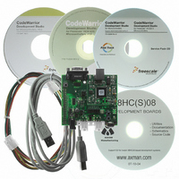
BOARD DEMO FOR 9S08 EL MCU
Manufacturer
Freescale Semiconductor
Type
MCUr
Datasheets
1.DEMO9S08EL32.pdf
(356 pages)
2.DEMO9S08EL32.pdf
(14 pages)
3.DEMO9S08EL32.pdf
(2 pages)
Specifications of DEMO9S08EL32
Contents
Evaluation Board
Processor To Be Evaluated
MC9S08EL32
Data Bus Width
8 bit
Interface Type
RS-232, USB
Operating Supply Voltage
12 V
Silicon Manufacturer
Freescale
Core Architecture
HCS08
Core Sub-architecture
HCS08
Silicon Core Number
MC9S08
Silicon Family Name
S08EL
Rohs Compliant
Yes
For Use With/related Products
MC9S08EL32
Lead Free Status / RoHS Status
Lead free / RoHS Compliant


11.4
This section provides a complete functional description of the IIC module.
11.4.1
The IIC bus system uses a serial data line (SDA) and a serial clock line (SCL) for data transfer. All devices
connected to it must have open drain or open collector outputs. A logic AND function is exercised on both
lines with external pull-up resistors. The value of these resistors is system dependent.
Normally, a standard communication is composed of four parts:
The stop signal should not be confused with the CPU stop instruction. The IIC bus system communication
is described briefly in the following sections and illustrated in
11.4.1.1
When the bus is free, no master device is engaging the bus (SCL and SDA lines are at logical high), a
master may initiate communication by sending a start signal. As shown in
defined as a high-to-low transition of SDA while SCL is high. This signal denotes the beginning of a new
data transfer (each data transfer may contain several bytes of data) and brings all slaves out of their idle
states.
Freescale Semiconductor
•
•
•
•
SCL
SDA
SCL
SDA
Start signal
Slave address transmission
Data transfer
Stop signal
Functional Description
Signal
Signal
Start
Start
IIC Protocol
Start Signal
msb
AD7 AD6 AD5 AD4 AD3 AD2 AD1 R/W
msb
AD7 AD6 AD5 AD4 AD3 AD2 AD1 R/W
1
1
2
2
Calling Address
Calling Address
3
3
MC9S08EL32 Series and MC9S08SL16 Series Data Sheet, Rev. 3
4
4
5
5
Figure 11-9. IIC Bus Transmission Signals
6
6
7
7
Read/
Read/
Write
Write
lsb
lsb
8
8
Ack
Ack
Bit
9
Bit
9
XX
Repeated
XXX
Signal
Start
msb
msb
AD7 AD6 AD5 AD4 AD3 AD2 AD1 R/W
D7
1
1
Figure
D6
2
2
New Calling Address
D5
3
3
11-9.
Data Byte
D4
4
4
D3
Figure
5
5
Inter-Integrated Circuit (S08IICV2)
D2
6
6
11-9, a start signal is
D1
7
7
Read/
Write
lsb
lsb
D0
8
8
Ack
No
Bit
Ack
No
9
Bit
9
Signal
Stop
Signal
Stop
175
Related parts for DEMO9S08EL32
Image
Part Number
Description
Manufacturer
Datasheet
Request
R

Part Number:
Description:
Manufacturer:
Freescale Semiconductor, Inc
Datasheet:
Part Number:
Description:
Manufacturer:
Freescale Semiconductor, Inc
Datasheet:
Part Number:
Description:
Manufacturer:
Freescale Semiconductor, Inc
Datasheet:
Part Number:
Description:
Manufacturer:
Freescale Semiconductor, Inc
Datasheet:
Part Number:
Description:
Manufacturer:
Freescale Semiconductor, Inc
Datasheet:
Part Number:
Description:
Manufacturer:
Freescale Semiconductor, Inc
Datasheet:
Part Number:
Description:
Manufacturer:
Freescale Semiconductor, Inc
Datasheet:
Part Number:
Description:
Manufacturer:
Freescale Semiconductor, Inc
Datasheet:
Part Number:
Description:
Manufacturer:
Freescale Semiconductor, Inc
Datasheet:
Part Number:
Description:
Manufacturer:
Freescale Semiconductor, Inc
Datasheet:
Part Number:
Description:
Manufacturer:
Freescale Semiconductor, Inc
Datasheet:
Part Number:
Description:
Manufacturer:
Freescale Semiconductor, Inc
Datasheet:
Part Number:
Description:
Manufacturer:
Freescale Semiconductor, Inc
Datasheet:
Part Number:
Description:
Manufacturer:
Freescale Semiconductor, Inc
Datasheet:
Part Number:
Description:
Manufacturer:
Freescale Semiconductor, Inc
Datasheet: