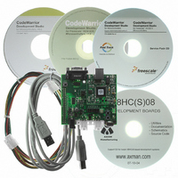
DEMO9S08EL32 Freescale Semiconductor, DEMO9S08EL32 Datasheet - Page 215

DEMO9S08EL32
Manufacturer Part Number
DEMO9S08EL32
Description
BOARD DEMO FOR 9S08 EL MCU
Manufacturer
Freescale Semiconductor
Type
MCUr
Datasheets
1.DEMO9S08EL32.pdf
(356 pages)
2.DEMO9S08EL32.pdf
(14 pages)
3.DEMO9S08EL32.pdf
(2 pages)
Specifications of DEMO9S08EL32
Contents
Evaluation Board
Processor To Be Evaluated
MC9S08EL32
Data Bus Width
8 bit
Interface Type
RS-232, USB
Operating Supply Voltage
12 V
Silicon Manufacturer
Freescale
Core Architecture
HCS08
Core Sub-architecture
HCS08
Silicon Core Number
MC9S08
Silicon Family Name
S08EL
Rohs Compliant
Yes
For Use With/related Products
MC9S08EL32
Lead Free Status / RoHS Status
Lead free / RoHS Compliant
- Current page: 215 of 356
- Download datasheet (9Mb)
The SLIC module cannot begin to transmit the data until the user writes a 1 to TXGO, indicating that data
is ready. If the user writes TXGO without loading data into the transmit buffer, whatever data is in storage
will be transmitted, where the number of bytes transmitted is based on the data length value in the data
length register. Similarly, if the user writes the wrong value for the number of data bytes to transmit, the
SLIC will transmit that number of bytes, potentially transmitting garbage data onto the bus. The checksum
calculation is performed based on the data transmitted, and will therefore still be calculated.
The identifier must be processed, data must be loaded into the transmit buffer, and the SLCDLC value
written to initiate data transmission in a certain amount of time, based on the LIN specification. If the user
waits too long to start transmission, the master node will observe an idle bus and trigger a Slave Not
Responding error condition. The same error can be triggered if the transmission begins too late and does
not complete before the message frame times out. Refer to the LIN specification for more details on timing
constraints and requirements for LIN slave devices. This is especially important when dealing with
extended request frames, when the data must be loaded in 8 byte sections (maximum) to be transmitted at
each interrupt.
12.6.9.2
Extended Request Message Frames
Handling of extended frames is very similar to handling of standard frames, providing that the length is
less than or equal to 64 bytes. Because the SLIC module can only transmit 8 bytes at a time, the transmit
buffer must be loaded periodically for extended message frames. This is not standard LIN operation, and
is likely only to be used for special cases, so the added steps required for processing should not be as
critical to performance. During these types of operations, the application code is likely very limited in
scope and special adjustments can be made to compensate for added message processing time.
When handling extended request frames, it is important to clear the SLCF flag first, before loading any
data or writing TXGO. The data length is still written only one time, at the time the identifier is decoded,
along with the TXGO and CHKMOD bits, after the first 8 data bytes are loaded into the transmit buffer.
When this is done, a software counter must also be initialized to keep track of how many bytes are to be
transmitted in the message frame. The SLIC will generate an interrupt, if unmasked, after 8 bytes are
transmitted or an error is detected. At this interrupt, the SLCSV will indicate an error condition (in case of
byte framing error or bit error) or that the transmit buffer is empty. If the data is transmitted successfully,
the user must then clear the SLCF flag, subtract 8 from the software byte count, load the next 8 bytes into
the SLCD registers, and write a 1 to TXGO to tell the SLIC that the buffers are loaded and transmission
can commence. When this software counter reaches 8 or fewer, the remaining data bytes will fit in the
transmit buffer and the SLIC will automatically append the checksum value to the frame after the last byte
is sent.
MC9S08EL32 Series and MC9S08SL16 Series Data Sheet, Rev. 3
Freescale Semiconductor
217
Related parts for DEMO9S08EL32
Image
Part Number
Description
Manufacturer
Datasheet
Request
R
Part Number:
Description:
Manufacturer:
Freescale Semiconductor, Inc
Datasheet:
Part Number:
Description:
Manufacturer:
Freescale Semiconductor, Inc
Datasheet:
Part Number:
Description:
Manufacturer:
Freescale Semiconductor, Inc
Datasheet:
Part Number:
Description:
Manufacturer:
Freescale Semiconductor, Inc
Datasheet:
Part Number:
Description:
Manufacturer:
Freescale Semiconductor, Inc
Datasheet:
Part Number:
Description:
Manufacturer:
Freescale Semiconductor, Inc
Datasheet:
Part Number:
Description:
Manufacturer:
Freescale Semiconductor, Inc
Datasheet:
Part Number:
Description:
Manufacturer:
Freescale Semiconductor, Inc
Datasheet:
Part Number:
Description:
Manufacturer:
Freescale Semiconductor, Inc
Datasheet:
Part Number:
Description:
Manufacturer:
Freescale Semiconductor, Inc
Datasheet:
Part Number:
Description:
Manufacturer:
Freescale Semiconductor, Inc
Datasheet:
Part Number:
Description:
Manufacturer:
Freescale Semiconductor, Inc
Datasheet:
Part Number:
Description:
Manufacturer:
Freescale Semiconductor, Inc
Datasheet:
Part Number:
Description:
Manufacturer:
Freescale Semiconductor, Inc
Datasheet:
Part Number:
Description:
Manufacturer:
Freescale Semiconductor, Inc
Datasheet:


