DEMO9S08EL32 Freescale Semiconductor, DEMO9S08EL32 Datasheet - Page 192
DEMO9S08EL32
Manufacturer Part Number
DEMO9S08EL32
Description
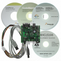
BOARD DEMO FOR 9S08 EL MCU
Manufacturer
Freescale Semiconductor
Type
MCUr
Datasheets
1.DEMO9S08EL32.pdf
(356 pages)
2.DEMO9S08EL32.pdf
(14 pages)
3.DEMO9S08EL32.pdf
(2 pages)
Specifications of DEMO9S08EL32
Contents
Evaluation Board
Processor To Be Evaluated
MC9S08EL32
Data Bus Width
8 bit
Interface Type
RS-232, USB
Operating Supply Voltage
12 V
Silicon Manufacturer
Freescale
Core Architecture
HCS08
Core Sub-architecture
HCS08
Silicon Core Number
MC9S08
Silicon Family Name
S08EL
Rohs Compliant
Yes
For Use With/related Products
MC9S08EL32
Lead Free Status / RoHS Status
Lead free / RoHS Compliant


1
194
SLCWCM
To guarantee timing, the user must ensure that the SLIC clock used allows the proper communications timing tolerances and
therefore internal oscillator circuits might not be appropriate for use with BTM mode.
RXFP
SLCE
BTM
Field
6:4
3
2
0
1
Receive Filter Prescaler — These bits configure the effective filter width for the digital receive filter circuit. The
RXFP bits control the maximum number of SLIC clock counts required for the filter to change state, which
determines the total maximum filter delay. Any pulse which is smaller than the maximum filter delay value will be
rejected by the filter and ignored as noise. For this reason, the user must choose the prescaler value
appropriately to ensure that all valid message traffic is able to pass the filter for the desired bit rate. For more
details about setting up the digital receive filter, please refer to
The frequency of the SLIC clock must be between 2 MHz and 20 MHz, factoring in worst case possible numbers
due to untrimmed process variations, as well as temperature and voltage variations in oscillator frequency. This
will guarantee greater than 1.5% accuracy for all LIN messages from 1–20 kbps. The faster this input clock is,
the greater the resulting accuracy and the higher the possible bit rates at which the SLIC can send and receive.
In LIN systems, the bit rates will not exceed 20 kbps; however, the SLIC module is capable of much higher speeds
without any configuration changes, for cases such as high-speed downloads for reprogramming of FLASH
memory or diagnostics in a test environment where radiated emissions requirements are not as stringent. In
these situations, the user may choose to run faster than the 20 kbps limit which is imposed by the LIN
specification for EMC reasons. Details of how to calculate maximum bit rates and operate the SLIC above 20
kbps are detailed in .” Refer to
when to set up this register. See
SLIC Wait Clock Mode — This write-once bit can only be written once out of MCU reset state and should be
written before SLIC is first enabled.
0 SLIC clocks continue to run when the CPU is placed into wait mode so that the SLIC can receive messages
1 SLIC clocks stop when the CPU is placed into wait mode
UART Byte Transfer Mode — Byte transmit mode bypasses the normal LIN message framing and checksum
monitoring and allows the user to send and receive single bytes in a method similar to a half-duplex UART. When
enabled, this mode reads the bit time register (SLCBT) value and assumes this is the value corresponding to the
number of SLIC clock counts for one bit time to establish the desired UART bit rate. The user software must
initialize this register prior to sending or receiving data, based on the input clock selection, prescaler stage
choice, and desired bit rate. If this bit is cleared during a byte transmission, that byte transmission is halted
immediately.
BTM treats any data length in SLCDLC as one byte (DLC = 0x00) and disables the checksum circuitry so that
CHKMOD has no effect. Refer to
about how to use this mode. BTM sets up the SLIC module to send and receive one byte at a time, with 8-bit
data, no parity, and one stop bit (8-N-1). This is the most commonly used setup for UART communications and
should work for most applications. This is fixed in the SLIC and is not configurable.
0 UART byte transfer mode disabled
1 UART byte transfer mode enabled
SLIC Module Enable — Controls the clock to the SLIC module
0 SLIC module disabled
1 SLIC module enabled
and wakeup the CPU.
MC9S08EL32 Series and MC9S08SL16 Series Data Sheet, Rev. 3
Table 12-2. SLCC2 Field Descriptions
Section 12.6.6, “SLIC Module Initialization
Section 12.6.16, “Byte Transfer Mode
Table
12-3.
Description
Section 12.6.18, “Digital Receive
Operation,” for more detailed information
Procedure,” for more information on
Freescale Semiconductor
Filter.”
Related parts for DEMO9S08EL32
Image
Part Number
Description
Manufacturer
Datasheet
Request
R

Part Number:
Description:
Manufacturer:
Freescale Semiconductor, Inc
Datasheet:
Part Number:
Description:
Manufacturer:
Freescale Semiconductor, Inc
Datasheet:
Part Number:
Description:
Manufacturer:
Freescale Semiconductor, Inc
Datasheet:
Part Number:
Description:
Manufacturer:
Freescale Semiconductor, Inc
Datasheet:
Part Number:
Description:
Manufacturer:
Freescale Semiconductor, Inc
Datasheet:
Part Number:
Description:
Manufacturer:
Freescale Semiconductor, Inc
Datasheet:
Part Number:
Description:
Manufacturer:
Freescale Semiconductor, Inc
Datasheet:
Part Number:
Description:
Manufacturer:
Freescale Semiconductor, Inc
Datasheet:
Part Number:
Description:
Manufacturer:
Freescale Semiconductor, Inc
Datasheet:
Part Number:
Description:
Manufacturer:
Freescale Semiconductor, Inc
Datasheet:
Part Number:
Description:
Manufacturer:
Freescale Semiconductor, Inc
Datasheet:
Part Number:
Description:
Manufacturer:
Freescale Semiconductor, Inc
Datasheet:
Part Number:
Description:
Manufacturer:
Freescale Semiconductor, Inc
Datasheet:
Part Number:
Description:
Manufacturer:
Freescale Semiconductor, Inc
Datasheet:
Part Number:
Description:
Manufacturer:
Freescale Semiconductor, Inc
Datasheet: