DEMO9S08EL32 Freescale Semiconductor, DEMO9S08EL32 Datasheet - Page 155
DEMO9S08EL32
Manufacturer Part Number
DEMO9S08EL32
Description
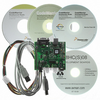
BOARD DEMO FOR 9S08 EL MCU
Manufacturer
Freescale Semiconductor
Type
MCUr
Datasheets
1.DEMO9S08EL32.pdf
(356 pages)
2.DEMO9S08EL32.pdf
(14 pages)
3.DEMO9S08EL32.pdf
(2 pages)
Specifications of DEMO9S08EL32
Contents
Evaluation Board
Processor To Be Evaluated
MC9S08EL32
Data Bus Width
8 bit
Interface Type
RS-232, USB
Operating Supply Voltage
12 V
Silicon Manufacturer
Freescale
Core Architecture
HCS08
Core Sub-architecture
HCS08
Silicon Core Number
MC9S08
Silicon Family Name
S08EL
Rohs Compliant
Yes
For Use With/related Products
MC9S08EL32
Lead Free Status / RoHS Status
Lead free / RoHS Compliant


result of the conversion is transferred to ADCRH and ADCRL upon completion of the conversion
algorithm.
If the bus frequency is less than the f
cannot be guaranteed when short sample is enabled (ADLSMP=0). If the bus frequency is less than 1/11th
of the f
sample is enabled (ADLSMP=1).
The maximum total conversion time for different conditions is summarized in
The maximum total conversion time is determined by the clock source chosen and the divide ratio selected.
The clock source is selectable by the ADICLK bits, and the divide ratio is specified by the ADIV bits. For
example, in 10-bit mode, with the bus clock selected as the input clock source, the input clock divide-by-1
ratio selected, and a bus frequency of 8 MHz, then the conversion time for a single conversion is:
Freescale Semiconductor
ADCK
Single or first continuous 10-bit
Single or first continuous 10-bit
Single or first continuous 10-bit
Single or first continuous 10-bit
Subsequent continuous 10-bit;
Subsequent continuous 10-bit;
Single or first continuous 8-bit
Single or first continuous 8-bit
Single or first continuous 8-bit
Single or first continuous 8-bit
Subsequent continuous 8-bit;
Subsequent continuous 8-bit;
frequency, precise sample time for continuous conversions cannot be guaranteed when long
Conversion Type
Conversion time =
f
f
The ADCK frequency must be between f
maximum to meet ADC specifications.
BUS
BUS
f
f
BUS
BUS
> f
> f
> f
> f
ADCK
ADCK
ADCK
ADCK
Number of bus cycles = 3.5 μs x 8 MHz = 28 cycles
Table 10-12. Total Conversion Time vs. Control Conditions
MC9S08EL32 Series and MC9S08SL16 Series Data Sheet, Rev. 3
/11
/11
ADCK
23 ADCK cyc
8 MHz/1
frequency, precise sample time for continuous conversions
ADICLK
0x, 10
0x, 10
0x, 10
0x, 10
11
11
11
11
xx
xx
xx
xx
NOTE
ADLSMP
+
ADCK
0
0
1
1
0
0
1
1
0
0
1
1
5 bus cyc
minimum and f
8 MHz
43 ADCK cycles + 5 bus clock cycles
20 ADCK cycles + 5 bus clock cycles
23 ADCK cycles + 5 bus clock cycles
40 ADCK cycles + 5 bus clock cycles
5 μs + 20 ADCK + 5 bus clock cycles
5 μs + 23 ADCK + 5 bus clock cycles
5 μs + 40 ADCK + 5 bus clock cycles
5 μs + 43 ADCK + 5 bus clock cycles
Analog-to-Digital Converter (S08ADC10V1)
Max Total Conversion Time
= 3.5 μs
17 ADCK cycles
20 ADCK cycles
37 ADCK cycles
40 ADCK cycles
ADCK
Table
10-12.
155
Related parts for DEMO9S08EL32
Image
Part Number
Description
Manufacturer
Datasheet
Request
R

Part Number:
Description:
Manufacturer:
Freescale Semiconductor, Inc
Datasheet:
Part Number:
Description:
Manufacturer:
Freescale Semiconductor, Inc
Datasheet:
Part Number:
Description:
Manufacturer:
Freescale Semiconductor, Inc
Datasheet:
Part Number:
Description:
Manufacturer:
Freescale Semiconductor, Inc
Datasheet:
Part Number:
Description:
Manufacturer:
Freescale Semiconductor, Inc
Datasheet:
Part Number:
Description:
Manufacturer:
Freescale Semiconductor, Inc
Datasheet:
Part Number:
Description:
Manufacturer:
Freescale Semiconductor, Inc
Datasheet:
Part Number:
Description:
Manufacturer:
Freescale Semiconductor, Inc
Datasheet:
Part Number:
Description:
Manufacturer:
Freescale Semiconductor, Inc
Datasheet:
Part Number:
Description:
Manufacturer:
Freescale Semiconductor, Inc
Datasheet:
Part Number:
Description:
Manufacturer:
Freescale Semiconductor, Inc
Datasheet:
Part Number:
Description:
Manufacturer:
Freescale Semiconductor, Inc
Datasheet:
Part Number:
Description:
Manufacturer:
Freescale Semiconductor, Inc
Datasheet:
Part Number:
Description:
Manufacturer:
Freescale Semiconductor, Inc
Datasheet:
Part Number:
Description:
Manufacturer:
Freescale Semiconductor, Inc
Datasheet: