DEMO9S08EL32 Freescale Semiconductor, DEMO9S08EL32 Datasheet - Page 201
DEMO9S08EL32
Manufacturer Part Number
DEMO9S08EL32
Description
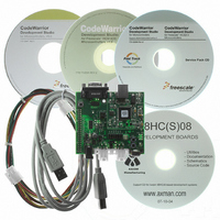
BOARD DEMO FOR 9S08 EL MCU
Manufacturer
Freescale Semiconductor
Type
MCUr
Datasheets
1.DEMO9S08EL32.pdf
(356 pages)
2.DEMO9S08EL32.pdf
(14 pages)
3.DEMO9S08EL32.pdf
(2 pages)
Specifications of DEMO9S08EL32
Contents
Evaluation Board
Processor To Be Evaluated
MC9S08EL32
Data Bus Width
8 bit
Interface Type
RS-232, USB
Operating Supply Voltage
12 V
Silicon Manufacturer
Freescale
Core Architecture
HCS08
Core Sub-architecture
HCS08
Silicon Core Number
MC9S08
Silicon Family Name
S08EL
Rohs Compliant
Yes
For Use With/related Products
MC9S08EL32
Lead Free Status / RoHS Status
Lead free / RoHS Compliant


12.3.7
The SLIC identifier (SLCID) and eight data registers (SLCD7–SLCD0) comprise the transmit and receive
buffer and are used to read/write the identifier and message buffer 8 data bytes. In BTM mode (BTM = 1),
only SLCID is used to send and receive bytes, as only one byte is handled at any one time. The number of
bytes to be read from or written to these registers is determined by the user software and written to
SLCDLC. To obtain proper data, reads and writes to these registers must be made based on the proper
length corresponding to a particular message. It is the responsibility of the user software to keep track of
this value to prevent data corruption. For example, it is possible to read data from locations in the message
buffer which contain erroneous or old data if the user software reads more data registers than were updated
by the incoming message, as indicated in SLCDLC.
The first data byte received after the LIN identifier in a LIN message frame will be loaded into SLCD0.
The next byte (if applicable) will be loaded into SLCD1, and so forth.
The SLIC identifier register is used to capture the incoming LIN identifier and when the SLCSV value
indicates that the identifier has been received successfully, this register contains the received identifier
value. If the incoming identifier contained a parity error, this register value will not contain valid data.
In byte transfer mode (BTM = 1), this register is used for sending and receiving each byte of data. When
transmitting bytes, the data is loaded into this register, then TXGO in SLCDLC is set to initiate the
transmission. When receiving bytes, they are read from this register only.
Freescale Semiconductor
Reset
W
R
SLIC Identifier and Data Registers (SLCID, SLCD7-SLCD0)
An incorrect length value written to SLCDLC can result in the user software
misreading or miswriting data in the message buffer. An incorrect length
value might also result in SLIC error messages. For example, if a 4-byte
message is to be received, but the user software incorrectly reports a 3-byte
length to the DLC, the SLIC will assume the 4th data byte is actually a
checksum value and attempt to validate it as such. If this value doesn’t
match the calculated value, an incorrect checksum error will occur. If it does
happen to match the expected value, then the message would be received as
a 3-byte message with valid checksum. Either case is incorrect behavior for
the application and can be avoided by ensuring that the correct length code
is used for each identifier.
R7
T7
0
7
MC9S08EL32 Series and MC9S08SL16 Series Data Sheet, Rev. 3
R6
T6
6
0
Figure 12-11. SLIC Identifier Register (SLCID)
R5
T5
0
5
NOTE
R4
T4
4
0
R3
T3
0
3
R2
T2
2
0
R1
T1
0
1
R0
T0
0
0
203
Related parts for DEMO9S08EL32
Image
Part Number
Description
Manufacturer
Datasheet
Request
R

Part Number:
Description:
Manufacturer:
Freescale Semiconductor, Inc
Datasheet:
Part Number:
Description:
Manufacturer:
Freescale Semiconductor, Inc
Datasheet:
Part Number:
Description:
Manufacturer:
Freescale Semiconductor, Inc
Datasheet:
Part Number:
Description:
Manufacturer:
Freescale Semiconductor, Inc
Datasheet:
Part Number:
Description:
Manufacturer:
Freescale Semiconductor, Inc
Datasheet:
Part Number:
Description:
Manufacturer:
Freescale Semiconductor, Inc
Datasheet:
Part Number:
Description:
Manufacturer:
Freescale Semiconductor, Inc
Datasheet:
Part Number:
Description:
Manufacturer:
Freescale Semiconductor, Inc
Datasheet:
Part Number:
Description:
Manufacturer:
Freescale Semiconductor, Inc
Datasheet:
Part Number:
Description:
Manufacturer:
Freescale Semiconductor, Inc
Datasheet:
Part Number:
Description:
Manufacturer:
Freescale Semiconductor, Inc
Datasheet:
Part Number:
Description:
Manufacturer:
Freescale Semiconductor, Inc
Datasheet:
Part Number:
Description:
Manufacturer:
Freescale Semiconductor, Inc
Datasheet:
Part Number:
Description:
Manufacturer:
Freescale Semiconductor, Inc
Datasheet:
Part Number:
Description:
Manufacturer:
Freescale Semiconductor, Inc
Datasheet: