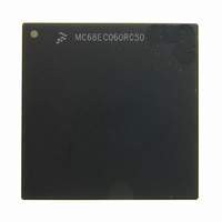
MC68EC060RC50 Freescale Semiconductor, MC68EC060RC50 Datasheet - Page 295

MC68EC060RC50
Manufacturer Part Number
MC68EC060RC50
Description
IC MPU 32BIT 50MHZ 206-PGA
Manufacturer
Freescale Semiconductor
Specifications of MC68EC060RC50
Processor Type
M680x0 32-Bit
Speed
50MHz
Voltage
3.3V
Mounting Type
Surface Mount
Package / Case
206-PGA
Family Name
M68000
Device Core
ColdFire
Device Core Size
32b
Frequency (max)
50MHz
Instruction Set Architecture
RISC
Supply Voltage 1 (typ)
3.3V
Operating Supply Voltage (max)
3.465V
Operating Supply Voltage (min)
3.135V
Operating Temp Range
0C to 110C
Operating Temperature Classification
Commercial
Mounting
Through Hole
Pin Count
206
Package Type
PGA
Lead Free Status / RoHS Status
Contains lead / RoHS non-compliant
Features
-
Lead Free Status / Rohs Status
Compliant
Available stocks
Company
Part Number
Manufacturer
Quantity
Price
Company:
Part Number:
MC68EC060RC50
Manufacturer:
NXP
Quantity:
1 746
- Current page: 295 of 416
- Download datasheet (2Mb)
IEEE 1149.1 Test (JTAG) and Debug Pipe Control Modes
9-34
STATE
JTAG
TRST
TCK
TMS
CLK
TDI
NOTES:
1. Clock is shown at 2x TCK here for illustration. Any relationship may exist but 3 full rising edges of CLK should occur after JTAG
2. When JTAG goes high, the MC68060 goes from "functional with JTAG" to "functional with DEBUG". When going to DEBUG
3. Hold TRST = H across boundary to prevent PAPPLY.
4. Hold TMS = H across boundary to keep JTAG in TLR.
5. After the boundary, PAPPLY must be negated before PDISABLE negates.
goes high and before PSHIFT or PDISABLE change.
modes the JTAG package pins remap to:
TRST
TDI
TMS
TCK
Figure 9-12. Transition from JTAG to Debug Mode Timing Diagram
1
PDISABLE
PAPPLY
PTDI
PSHIFT
SeIR
2
ALL "P" signals internally negated when JTAG = low.
2
JTAG MODE
TLR
3
4
JTAG MUST BE IN TLR
3
5
TLR
M68060 USER’S MANUAL
6
4
TLR
7
8
DISABLED
9
DEBUG MODE
10
11
SHIFT
12
13
SHIFT
14
MOTOROLA
APPLY
CLK
PSHIFT
JTAG
PDISABLE
PAPPLY
PTDI
ACTION
Related parts for MC68EC060RC50
Image
Part Number
Description
Manufacturer
Datasheet
Request
R
Part Number:
Description:
Manufacturer:
Freescale Semiconductor, Inc
Datasheet:
Part Number:
Description:
Manufacturer:
Freescale Semiconductor, Inc
Datasheet:
Part Number:
Description:
Manufacturer:
Freescale Semiconductor, Inc
Datasheet:
Part Number:
Description:
Manufacturer:
Freescale Semiconductor, Inc
Datasheet:
Part Number:
Description:
Manufacturer:
Freescale Semiconductor, Inc
Datasheet:
Part Number:
Description:
Manufacturer:
Freescale Semiconductor, Inc
Datasheet:
Part Number:
Description:
Manufacturer:
Freescale Semiconductor, Inc
Datasheet:
Part Number:
Description:
Manufacturer:
Freescale Semiconductor, Inc
Datasheet:
Part Number:
Description:
Manufacturer:
Freescale Semiconductor, Inc
Datasheet:
Part Number:
Description:
Manufacturer:
Freescale Semiconductor, Inc
Datasheet:
Part Number:
Description:
Manufacturer:
Freescale Semiconductor, Inc
Datasheet:
Part Number:
Description:
Manufacturer:
Freescale Semiconductor, Inc
Datasheet:
Part Number:
Description:
Manufacturer:
Freescale Semiconductor, Inc
Datasheet:
Part Number:
Description:
Manufacturer:
Freescale Semiconductor, Inc
Datasheet:
Part Number:
Description:
Manufacturer:
Freescale Semiconductor, Inc
Datasheet:


