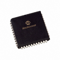
PIC18F452-I/LG Microchip Technology, PIC18F452-I/LG Datasheet - Page 325

PIC18F452-I/LG
Manufacturer Part Number
PIC18F452-I/LG
Description
IC MCU FLASH 16KX16 W/AD 44PLCC
Manufacturer
Microchip Technology
Series
PIC® 18Fr
Datasheets
1.PIC16F616T-ISL.pdf
(8 pages)
2.PIC18F242-ISO.pdf
(332 pages)
3.PIC18F242-ISO.pdf
(14 pages)
4.PIC18F242-ISO.pdf
(16 pages)
5.PIC18F242-ISO.pdf
(16 pages)
6.PIC18F242-ISO.pdf
(14 pages)
7.PIC18LF242-ISO.pdf
(36 pages)
Specifications of PIC18F452-I/LG
Core Processor
PIC
Core Size
8-Bit
Speed
40MHz
Connectivity
I²C, SPI, UART/USART
Peripherals
Brown-out Detect/Reset, LVD, POR, PWM, WDT
Number Of I /o
34
Program Memory Size
32KB (16K x 16)
Program Memory Type
FLASH
Eeprom Size
256 x 8
Ram Size
1.5K x 8
Voltage - Supply (vcc/vdd)
4.2 V ~ 5.5 V
Data Converters
A/D 8x10b
Oscillator Type
External
Operating Temperature
-40°C ~ 85°C
Package / Case
44-PLCC
For Use With
XLT44L2 - SOCKET TRAN ICE 44PLCCDVA16XL441 - ADAPTER DEVICE ICE 44PLCC
Lead Free Status / RoHS Status
Lead free / RoHS Compliant
RETFIE ............................................................................ 242
RETLW ............................................................................. 242
RETURN .......................................................................... 243
Revision History ............................................................... 313
RLCF ................................................................................ 243
RLNCF ............................................................................. 244
RRCF ............................................................................... 244
RRNCF ............................................................................. 245
S
SCI. See USART
SCK .................................................................................. 125
SDI ................................................................................... 125
SDO ................................................................................. 125
Serial Clock, SCK ............................................................. 125
Serial Communication Interface. See USART
Serial Data In, SDI ........................................................... 125
Serial Data Out, SDO ....................................................... 125
Serial Peripheral Interface. See SPI
SETF ................................................................................ 245
Slave Select Synchronization ........................................... 131
Slave Select, SS .............................................................. 125
SLEEP ...............................................................195, 205, 246
Software Simulator (MPLAB SIM) .................................... 254
Special Event Trigger. See Compare
Special Features of the CPU ............................................ 195
Special Function Registers ................................................ 42
SPI
SPI Master/Slave Connection .......................................... 129
SPI Module
SS .................................................................................... 125
SSP
SSPOV Status Flag .......................................................... 155
SSPSTAT Register
Status Bits
SUBFWB .......................................................................... 246
SUBLW ............................................................................ 247
SUBWF ............................................................................ 247
SUBWFB .......................................................................... 248
SWAPF ............................................................................ 248
© 2006 Microchip Technology Inc.
Configuration Registers ................................... 196–201
Map ............................................................................ 45
Master Mode ............................................................ 130
Serial Clock .............................................................. 125
Serial Data In ........................................................... 125
Serial Data Out ........................................................ 125
Slave Select ............................................................. 125
SPI Clock ................................................................. 130
SPI Mode ................................................................. 125
Associated Registers ............................................... 133
Bus Mode Compatibility ........................................... 133
Effects of a RESET .................................................. 133
Master/Slave Connection ......................................... 129
Slave Mode .............................................................. 131
Slave Select Synchronization .................................. 131
Slave Synch Timing ................................................. 131
SLEEP Operation ..................................................... 133
I
SPI Mode ................................................................. 125
SPI Mode. See SPI
SSPBUF Register .................................................... 130
SSPSR Register ...................................................... 130
TMR2 Output for Clock Shift ............................ 111, 112
R/W Bit ............................................................. 138, 139
Significance and the Initialization Condition
2
C Mode. See I
for RCON Register ............................................. 27
2
C
T
TABLAT Register ............................................................... 58
Table Pointer Operations (table) ........................................ 58
TBLPTR Register ............................................................... 58
TBLRD ............................................................................. 249
TBLWT ............................................................................. 250
Time-out Sequence ........................................................... 26
Timer0 .............................................................................. 103
Timer1 .............................................................................. 107
Timer2 .............................................................................. 111
Timer3 .............................................................................. 113
Timing Diagrams
Time-out in Various Situations ................................... 27
16-bit Mode Timer Reads and Writes ...................... 105
Associated Registers ............................................... 105
Clock Source Edge Select (T0SE Bit) ..................... 105
Clock Source Select (T0CS Bit) ............................... 105
Operation ................................................................. 105
Overflow Interrupt .................................................... 105
Prescaler. See Prescaler, Timer0
16-bit Read/Write Mode ........................................... 109
Associated Registers ............................................... 110
Operation ................................................................. 108
Oscillator ...........................................................107, 109
Overflow Interrupt .............................................107, 109
Special Event Trigger (CCP) ............................109, 120
TMR1H Register ...................................................... 107
TMR1L Register ....................................................... 107
Associated Registers ............................................... 112
Operation ................................................................. 111
Postscaler. See Postscaler, Timer2
PR2 Register ....................................................111, 122
Prescaler. See Prescaler, Timer2
SSP Clock Shift ................................................111, 112
TMR2 Register ......................................................... 111
TMR2 to PR2 Match Interrupt ................... 111, 112, 122
Associated Registers ............................................... 115
Operation ................................................................. 114
Oscillator ...........................................................113, 115
Overflow Interrupt .............................................113, 115
Special Event Trigger (CCP) ................................... 115
TMR3H Register ...................................................... 113
TMR3L Register ....................................................... 113
A/D Conversion ........................................................ 287
Acknowledge Sequence .......................................... 158
Baud Rate Generator with Clock Arbitration ............ 152
BRG Reset Due to SDA Arbitration During
Brown-out Reset (BOR) ........................................... 274
Bus Collision
Bus Collision During a Repeated
Bus Collision During a Repeated
Bus Collision During a START Condition
Bus Collision During a STOP Condition
Bus Collision During a STOP Condition
Capture/Compare/PWM (CCP1 and CCP2) ............ 276
CLKO and I/O .......................................................... 272
Clock Synchronization ............................................. 145
Bus Collision
START Condition ............................................. 161
Start Condition (SDA Only) .............................. 160
START Condition (Case 1) .............................. 162
START Condition (Case 2) .............................. 162
(SCL = 0) ......................................................... 161
(Case 1) ........................................................... 163
(Case 2) ........................................................... 163
Transmit and Acknowledge ..................... 159
PIC18FXX2
DS39564C-page 323


