MC56F8006DEMO Freescale Semiconductor, MC56F8006DEMO Datasheet - Page 8
MC56F8006DEMO
Manufacturer Part Number
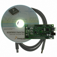
MC56F8006DEMO
Description
DEMO BOARD FOR MC56F8006
Manufacturer
Freescale Semiconductor
Type
DSPr
Datasheets
1.MC56F8006DEMO.pdf
(13 pages)
2.MC56F8006DEMO.pdf
(8 pages)
3.MC56F8006DEMO.pdf
(2 pages)
4.MC56F8006DEMO.pdf
(100 pages)
Specifications of MC56F8006DEMO
Contents
Board
Processor To Be Evaluated
MC56F8006
Interface Type
RS-232, USB
Operating Supply Voltage
3.3 V
Silicon Manufacturer
Freescale
Core Architecture
56800/E
Core Sub-architecture
56800/E
Silicon Core Number
MC56F
Silicon Family Name
MC56F80xx
Rohs Compliant
Yes
For Use With/related Products
MC56F8006
Lead Free Status / RoHS Status
Lead free / RoHS Compliant


Overview
3.1.6
3.2
Processor Expert
software application creation with an expert knowledge system.
The CodeWarrior Integrated Development Environment is a sophisticated tool for code navigation, compiling, and debugging.
A complete set of evaluation modules (EVMs), demonstration board kit, and development system cards support concurrent
engineering. Together, PE, CodeWarrior, and EVMs create a complete, scalable tools solution for easy, fast, and efficient
development.
A full set of programmable peripherals — PWM, PGAs, ADCs, SCI, SPI, I
various applications. Each peripheral can be independently shut down to save power. Any pin in these peripherals can also be
used as general-purpose input/outputs (GPIOs).
8
•
•
•
•
•
•
•
•
— On-chip relaxation oscillator with two user selectable frequencies: 400 kHz for low speed mode, 8 MHz for
— On-chip low-power 1 kHz oscillator can be selected as clock source to the RTC and/or COP
— External clock: crystal oscillator, ceramic resonator, and external clock source
Power management controller (PMC)
— On-chip regulator for digital and analog circuitry to lower cost and reduce noise
— Integrated power-on reset (POR)
— Low-voltage interrupt with a user selectable trip voltage of 1.81 V or 2.31 V
— User selectable brown-out reset
— Run, wait, and stop modes
— Low-power run, wait, and stop modes
— Partial power down mode
Up to 40 general-purpose I/O (GPIO) pins
— Individual control for each pin to be in peripheral or GPIO mode
— Individual input/output direction control for each pin in GPIO mode
— Hysteresis and configurable pullup device on all input pins
— Configurable slew rate and drive strength and optional input low pass filters on all output pins
— 20 mA sink/source current
JTAG/EOnCE debug programming interface for real-time debugging
— IEEE 1149.1 Joint Test Action Group (JTAG) interface
— EOnCE interface for real-time debugging
Three low power modes
— Low-speed run, wait, and stop modes: 200 kHz IP bus clock provided by ROSC
— Low-power run, wait, and stop modes: clock provided by external 32–38.4 kHz crystal
— Partial power down mode
Low power external oscillator can be used in any low-power mode to provide accurate clock to active peripherals
Low power real time counter for use in run, wait, and stop modes with internal and external clock sources
32 s typical wakeup time from partial power down modes
Each peripheral can be individually disabled to save power
Award-Winning Development Environment
normal operation
Power Saving Features
TM
(PE) provides a Rapid Application Design (RAD) tool that combines easy-to-use component-based
MC56F8006/MC56F8002 Digital Signal Controller, Rev. 3
2
C, PIT, timers, and analog comparators — supports
Freescale Semiconductor
Related parts for MC56F8006DEMO
Image
Part Number
Description
Manufacturer
Datasheet
Request
R

Part Number:
Description:
Manufacturer:
Freescale Semiconductor, Inc
Datasheet:
Part Number:
Description:
Manufacturer:
Freescale Semiconductor, Inc
Datasheet:
Part Number:
Description:
Manufacturer:
Freescale Semiconductor, Inc
Datasheet:
Part Number:
Description:
Manufacturer:
Freescale Semiconductor, Inc
Datasheet:
Part Number:
Description:
Manufacturer:
Freescale Semiconductor, Inc
Datasheet:
Part Number:
Description:
Manufacturer:
Freescale Semiconductor, Inc
Datasheet:
Part Number:
Description:
Manufacturer:
Freescale Semiconductor, Inc
Datasheet:
Part Number:
Description:
Manufacturer:
Freescale Semiconductor, Inc
Datasheet:
Part Number:
Description:
Manufacturer:
Freescale Semiconductor, Inc
Datasheet:
Part Number:
Description:
Manufacturer:
Freescale Semiconductor, Inc
Datasheet:
Part Number:
Description:
Manufacturer:
Freescale Semiconductor, Inc
Datasheet:
Part Number:
Description:
Manufacturer:
Freescale Semiconductor, Inc
Datasheet:
Part Number:
Description:
Manufacturer:
Freescale Semiconductor, Inc
Datasheet:
Part Number:
Description:
Manufacturer:
Freescale Semiconductor, Inc
Datasheet:
Part Number:
Description:
Manufacturer:
Freescale Semiconductor, Inc
Datasheet: