MC56F8006DEMO Freescale Semiconductor, MC56F8006DEMO Datasheet - Page 37
MC56F8006DEMO
Manufacturer Part Number
MC56F8006DEMO
Description
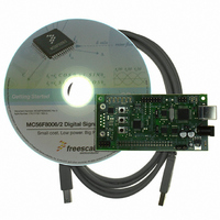
DEMO BOARD FOR MC56F8006
Manufacturer
Freescale Semiconductor
Type
DSPr
Datasheets
1.MC56F8006DEMO.pdf
(13 pages)
2.MC56F8006DEMO.pdf
(8 pages)
3.MC56F8006DEMO.pdf
(2 pages)
4.MC56F8006DEMO.pdf
(100 pages)
Specifications of MC56F8006DEMO
Contents
Board
Processor To Be Evaluated
MC56F8006
Interface Type
RS-232, USB
Operating Supply Voltage
3.3 V
Silicon Manufacturer
Freescale
Core Architecture
56800/E
Core Sub-architecture
56800/E
Silicon Core Number
MC56F
Silicon Family Name
MC56F80xx
Rohs Compliant
Yes
For Use With/related Products
MC56F8006
Lead Free Status / RoHS Status
Lead free / RoHS Compliant


6.7
The comparators, timers, and PWM_reload_sync output can be connected to the programmable delay block (PDB) trigger input.
The PDB pre-trigger A and trigger A outputs are connected to the ADCA and PGA0 hardware trigger inputs. The PDB
pre-trigger B and trigger B outputs are connected to the ADCB and PGA1 hardware trigger inputs. When the input trigger of
PDB is asserted, PDB trigger and pre-trigger outputs are asserted after a delay of a pre-programmed period. See the MC56F8006
Peripheral Reference Manual for additional information.
Freescale Semiconductor
•
•
•
•
•
•
•
•
•
•
•
•
•
ANA7
Registers containing the JTAG ID of the chip
Controls for programmable peripheral and GPIO connections
Peripheral clocks for TMR and PWM and SCI with a high-speed (3X) option
Power-saving clock gating for peripherals
Controls the enable/disable functions of large regulator standby mode with write protection capability
Permits selected peripherals to run in stop mode to generate stop recovery interrupts
Controls for programmable peripheral and GPIO connections
Software chip reset
I/O short address base location control
Peripheral protection control to provide runaway code protection for safety-critical applications
Controls output of internal clock sources to CLKO pin
Four general-purpose software control registers are reset only at power-on
Peripherals stop mode clocking control
System
Clock
ADCA
PWM, PDB, PGA, and ADC Connections
ANA9
Trigger0
CMP0
ADHWT
SSEL[0]
SSEL[1]
ANA15
Trigger1
MC56F8006/MC56F8002 Digital Signal Controller, Rev. 3
CMP1
ADCA
Trigger
PGA0 Controller
Figure 14. Synchronization of ADC, PDB
Programmable Delay Block (PDB)
TriggerA
Trigger2
CMP2
Pre-
TriggerA
Trigger3
PWM
Pre-
TriggerB
PGA1 Controller
Trigger4
EXT
TriggerB
TMR0
Trigger5
ADCB
Trigger
General System Control Information
ADHWT
SSEL[1]
ANB15 ANB8
SSEL[0]
TMR1
Trigger6
ADCB
Trigger7
SW
ANB6
37
Related parts for MC56F8006DEMO
Image
Part Number
Description
Manufacturer
Datasheet
Request
R

Part Number:
Description:
Manufacturer:
Freescale Semiconductor, Inc
Datasheet:
Part Number:
Description:
Manufacturer:
Freescale Semiconductor, Inc
Datasheet:
Part Number:
Description:
Manufacturer:
Freescale Semiconductor, Inc
Datasheet:
Part Number:
Description:
Manufacturer:
Freescale Semiconductor, Inc
Datasheet:
Part Number:
Description:
Manufacturer:
Freescale Semiconductor, Inc
Datasheet:
Part Number:
Description:
Manufacturer:
Freescale Semiconductor, Inc
Datasheet:
Part Number:
Description:
Manufacturer:
Freescale Semiconductor, Inc
Datasheet:
Part Number:
Description:
Manufacturer:
Freescale Semiconductor, Inc
Datasheet:
Part Number:
Description:
Manufacturer:
Freescale Semiconductor, Inc
Datasheet:
Part Number:
Description:
Manufacturer:
Freescale Semiconductor, Inc
Datasheet:
Part Number:
Description:
Manufacturer:
Freescale Semiconductor, Inc
Datasheet:
Part Number:
Description:
Manufacturer:
Freescale Semiconductor, Inc
Datasheet:
Part Number:
Description:
Manufacturer:
Freescale Semiconductor, Inc
Datasheet:
Part Number:
Description:
Manufacturer:
Freescale Semiconductor, Inc
Datasheet:
Part Number:
Description:
Manufacturer:
Freescale Semiconductor, Inc
Datasheet: