MC56F8006DEMO Freescale Semiconductor, MC56F8006DEMO Datasheet - Page 50
MC56F8006DEMO
Manufacturer Part Number
MC56F8006DEMO
Description
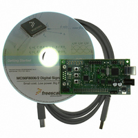
DEMO BOARD FOR MC56F8006
Manufacturer
Freescale Semiconductor
Type
DSPr
Datasheets
1.MC56F8006DEMO.pdf
(13 pages)
2.MC56F8006DEMO.pdf
(8 pages)
3.MC56F8006DEMO.pdf
(2 pages)
4.MC56F8006DEMO.pdf
(100 pages)
Specifications of MC56F8006DEMO
Contents
Board
Processor To Be Evaluated
MC56F8006
Interface Type
RS-232, USB
Operating Supply Voltage
3.3 V
Silicon Manufacturer
Freescale
Core Architecture
56800/E
Core Sub-architecture
56800/E
Silicon Core Number
MC56F
Silicon Family Name
MC56F80xx
Rohs Compliant
Yes
For Use With/related Products
MC56F8006
Lead Free Status / RoHS Status
Lead free / RoHS Compliant


Specifications
8.7
50
1
2
3
4
oscillator (1 kHz)
clock monitoring
No output switching; all ports configured as inputs; all inputs low; no DC loads.
Low speed mode: LPR (lower voltage regulator control bit) = 0 and voltage regulator is in full regulation. Characterization only.
Low power mode: LPR (lower voltage regulator control bit) = 1; the voltage regulator is put into standby.
Partial power down mode: PPDE (partial power down enable bit) = 1; power management controller (PMC) enters partial
power down mode the next time that the STOP command is executed.
PPD with LP
PPD with no
PPD
1
2
LSstop
LPstop
enabled
XOSC
Mode
There is additional overhead that is part of the programming sequence. See the MC56F8006 Peripheral Reference
Manual for detail.
Specifies page erase time. There are 512 bytes per page in the program flash memory.
4
with
Flash Memory Characteristics
2
2
Mass erase time
Characteristic
Program time
200 kHz device clock;
relaxation oscillator (ROSC) in standby mode;
PLL disabled;
all peripheral modules disabled and clock gated off;
processor core in stop state.
32.768 kHz device clock;
Clocked by a 32.768 kHz external crystal relaxation
oscillator (ROSC) in power down;
PLL disabled;
all peripheral modules disabled and clock gated off;
processor core in stop state.
32.768 kHz clock fed on XTAL
RTC or COP monitoring XOSC (but no wakeup)
processor core in stop state
RTC or COP monitoring LP oscillator (but no
wakeup);
processor core in stop state.
RTC and LP oscillator are disabled;
processor core in stop state.
Erase time
2
1
MC56F8006/MC56F8002 Digital Signal Controller, Rev. 3
Conditions
Table 21. Supply Current Consumption
Table 22. Flash Timing Parameters
Symbol
t
t
erase
prog
t
me
Min
100
20
20
194.69 A
879.72 nA
499.15 nA
494.04 nA
Typical @ 3.3 V, 25°C
2.77 A
I
DD
1
Typ
—
—
—
65.51 A
13.99 nA
11.56 nA
12.88 nA
13.9 nA
I
DDA
Max
40
—
—
Maximum @ 3.6 V, 25°C
Freescale Semiconductor
340 A
45 A
18 A
14 A
14 A
I
DD
1
Unit
ms
ms
s
120 A
3.0 A
2.4 A
2.4 A
2.4 A
I
DDA
Related parts for MC56F8006DEMO
Image
Part Number
Description
Manufacturer
Datasheet
Request
R

Part Number:
Description:
Manufacturer:
Freescale Semiconductor, Inc
Datasheet:
Part Number:
Description:
Manufacturer:
Freescale Semiconductor, Inc
Datasheet:
Part Number:
Description:
Manufacturer:
Freescale Semiconductor, Inc
Datasheet:
Part Number:
Description:
Manufacturer:
Freescale Semiconductor, Inc
Datasheet:
Part Number:
Description:
Manufacturer:
Freescale Semiconductor, Inc
Datasheet:
Part Number:
Description:
Manufacturer:
Freescale Semiconductor, Inc
Datasheet:
Part Number:
Description:
Manufacturer:
Freescale Semiconductor, Inc
Datasheet:
Part Number:
Description:
Manufacturer:
Freescale Semiconductor, Inc
Datasheet:
Part Number:
Description:
Manufacturer:
Freescale Semiconductor, Inc
Datasheet:
Part Number:
Description:
Manufacturer:
Freescale Semiconductor, Inc
Datasheet:
Part Number:
Description:
Manufacturer:
Freescale Semiconductor, Inc
Datasheet:
Part Number:
Description:
Manufacturer:
Freescale Semiconductor, Inc
Datasheet:
Part Number:
Description:
Manufacturer:
Freescale Semiconductor, Inc
Datasheet:
Part Number:
Description:
Manufacturer:
Freescale Semiconductor, Inc
Datasheet:
Part Number:
Description:
Manufacturer:
Freescale Semiconductor, Inc
Datasheet: