MC56F8006DEMO Freescale Semiconductor, MC56F8006DEMO Datasheet - Page 34
MC56F8006DEMO
Manufacturer Part Number
MC56F8006DEMO
Description
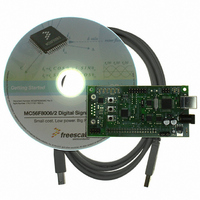
DEMO BOARD FOR MC56F8006
Manufacturer
Freescale Semiconductor
Type
DSPr
Datasheets
1.MC56F8006DEMO.pdf
(13 pages)
2.MC56F8006DEMO.pdf
(8 pages)
3.MC56F8006DEMO.pdf
(2 pages)
4.MC56F8006DEMO.pdf
(100 pages)
Specifications of MC56F8006DEMO
Contents
Board
Processor To Be Evaluated
MC56F8006
Interface Type
RS-232, USB
Operating Supply Voltage
3.3 V
Silicon Manufacturer
Freescale
Core Architecture
56800/E
Core Sub-architecture
56800/E
Silicon Core Number
MC56F
Silicon Family Name
MC56F80xx
Rohs Compliant
Yes
For Use With/related Products
MC56F8006
Lead Free Status / RoHS Status
Lead free / RoHS Compliant


General System Control Information
The clock generation module provides the programming interface for the PLL, internal relaxation oscillator, and crystal
oscillator. It also provides a postscaler to divide clock frequency down by 1, 2, 4, 8, 16, 32, 64, 128, 256 before feeding to the
SIM. The SIM is responsible for further dividing these frequencies by two, which ensures a 50% duty cycle in the system clock
output. For detail, see the OCCS chapter in the MC56F8006 Peripheral Reference Manual.
6.4.1
An internal relaxation oscillator can supply the reference frequency when an external frequency source or crystal is not used. It
is optimized for accuracy and programmability while providing several power-saving configurations that accommodate
different operating conditions. The internal relaxation oscillator has little temperature and voltage variability. To optimize
power, the internal relaxation oscillator supports a run state (8 MHz), standby state (400 kHz), and a power-down state.
During a boot or reset sequence, the relaxation oscillator is enabled by default (the PRECS bit in the PLLCR word is set to 0).
Application code can then also switch to the external clock source and power down the internal oscillator, if desired. If a
changeover between internal and external clock sources is required at power-on, ensure that the clock source is not switched
until the desired external clock source is enabled and stable.
To compensate for variances in the device manufacturing process, the accuracy of the relaxation oscillator can be incrementally
adjusted to within + 0.078% of 8 MHz by trimming an internal capacitor. Bits 0–9 of the OSCTL (oscillator control) register
allow you to set in an additional offset (trim) to this preset value to increase or decrease capacitance. Each unit added or
subtracted changes the output frequency by about 0.078% of 8 MHz, allowing incremental adjustment until the desired
frequency accuracy is achieved.
The center frequency of the internal oscillator is calibrated at the factory to 8 MHz and the TRIM value is stored in the flash
information block and loaded to the FMOPT1 register at reset. When using the relaxation oscillator, the boot code should read
the FMOPT1 register and set this value as OSCTL TRIM. For further information, see the MC56F8006 Peripheral Reference
Manual.
6.4.2
The internal crystal oscillator circuit is designed to interface with a parallel-resonant crystal resonator in the frequency range,
specified for the external crystal, of 32.768 kHz (Typ) or 1–16 MHz. A ceramic resonator can be substituted for the 1–16 MHz
range. When used to supply a source to the internal PLL, the recommended crystal/resonator is in the 4 MHz to 8 MHz
(recommend 8 MHz) range to achieve optimized PLL performance. Oscillator circuits are shown in
Figure
component values required to provide maximum stability and reliable start-up. The load capacitance values used in the
oscillator circuit design should include all stray layout capacitances. The crystal and associated components should be mounted
as near as possible to the EXTAL and XTAL pins to minimize output distortion and start-up stabilization time. When using
low-frequency, low-power mode, the only external component is the crystal itself. In the other oscillator modes, load capacitors
(C
Recommended component values are listed in
34
x
, C
•
•
•
y
11.
) and feedback resistor (R
Provides a 3X system clock that operates at three times the system clock to PWM, timer, and SCI modules
Safety shutdown feature is available if the PLL reference clock is lost
Can be driven from an external clock source
Follow the crystal supplier’s recommendations when selecting a crystal, because crystal parameters determine the
Internal Clock Source
Crystal Oscillator/Ceramic Resonator
F
MC56F8006/MC56F8002 Digital Signal Controller, Rev. 3
) are required. In addition, a series resistor (R
Table
27.
S
) may be used in high-gain modes.
Figure
Freescale Semiconductor
9,
Figure
10, and
Related parts for MC56F8006DEMO
Image
Part Number
Description
Manufacturer
Datasheet
Request
R

Part Number:
Description:
Manufacturer:
Freescale Semiconductor, Inc
Datasheet:
Part Number:
Description:
Manufacturer:
Freescale Semiconductor, Inc
Datasheet:
Part Number:
Description:
Manufacturer:
Freescale Semiconductor, Inc
Datasheet:
Part Number:
Description:
Manufacturer:
Freescale Semiconductor, Inc
Datasheet:
Part Number:
Description:
Manufacturer:
Freescale Semiconductor, Inc
Datasheet:
Part Number:
Description:
Manufacturer:
Freescale Semiconductor, Inc
Datasheet:
Part Number:
Description:
Manufacturer:
Freescale Semiconductor, Inc
Datasheet:
Part Number:
Description:
Manufacturer:
Freescale Semiconductor, Inc
Datasheet:
Part Number:
Description:
Manufacturer:
Freescale Semiconductor, Inc
Datasheet:
Part Number:
Description:
Manufacturer:
Freescale Semiconductor, Inc
Datasheet:
Part Number:
Description:
Manufacturer:
Freescale Semiconductor, Inc
Datasheet:
Part Number:
Description:
Manufacturer:
Freescale Semiconductor, Inc
Datasheet:
Part Number:
Description:
Manufacturer:
Freescale Semiconductor, Inc
Datasheet:
Part Number:
Description:
Manufacturer:
Freescale Semiconductor, Inc
Datasheet:
Part Number:
Description:
Manufacturer:
Freescale Semiconductor, Inc
Datasheet: