MC56F8006DEMO Freescale Semiconductor, MC56F8006DEMO Datasheet - Page 2
MC56F8006DEMO
Manufacturer Part Number
MC56F8006DEMO
Description
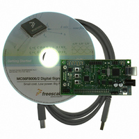
DEMO BOARD FOR MC56F8006
Manufacturer
Freescale Semiconductor
Type
DSPr
Datasheets
1.MC56F8006DEMO.pdf
(13 pages)
2.MC56F8006DEMO.pdf
(8 pages)
3.MC56F8006DEMO.pdf
(2 pages)
4.MC56F8006DEMO.pdf
(100 pages)
Specifications of MC56F8006DEMO
Contents
Board
Processor To Be Evaluated
MC56F8006
Interface Type
RS-232, USB
Operating Supply Voltage
3.3 V
Silicon Manufacturer
Freescale
Core Architecture
56800/E
Core Sub-architecture
56800/E
Silicon Core Number
MC56F
Silicon Family Name
MC56F80xx
Rohs Compliant
Yes
For Use With/related Products
MC56F8006
Lead Free Status / RoHS Status
Lead free / RoHS Compliant


1
2
3
4
5
6
7
8
2
MC56F8006/MC56F8002 Family Configuration . . . . . . . . . . . .3
Block Diagram . . . . . . . . . . . . . . . . . . . . . . . . . . . . . . . . . . . . .4
Overview. . . . . . . . . . . . . . . . . . . . . . . . . . . . . . . . . . . . . . . . . .4
3.1
3.2
3.3
3.4
Signal/Connection Descriptions . . . . . . . . . . . . . . . . . . . . . . .11
4.1
4.2
4.3
Memory Maps. . . . . . . . . . . . . . . . . . . . . . . . . . . . . . . . . . . . .28
5.1
5.2
5.3
5.4
5.5
5.6
General System Control Information . . . . . . . . . . . . . . . . . . .33
6.1
6.2
6.3
6.4
6.5
6.6
6.7
6.8
Security Features . . . . . . . . . . . . . . . . . . . . . . . . . . . . . . . . . .38
7.1
7.2
7.3
Specifications . . . . . . . . . . . . . . . . . . . . . . . . . . . . . . . . . . . . .40
56F8006/56F8002 Features . . . . . . . . . . . . . . . . . . . . . .4
Award-Winning Development Environment. . . . . . . . . . .8
Architecture Block Diagram. . . . . . . . . . . . . . . . . . . . . . .9
Product Documentation . . . . . . . . . . . . . . . . . . . . . . . .11
Introduction . . . . . . . . . . . . . . . . . . . . . . . . . . . . . . . . . .11
Pin Assignment . . . . . . . . . . . . . . . . . . . . . . . . . . . . . . .13
56F8006/56F8002 Signal Pins . . . . . . . . . . . . . . . . . . .16
Introduction . . . . . . . . . . . . . . . . . . . . . . . . . . . . . . . . . .28
Program Map . . . . . . . . . . . . . . . . . . . . . . . . . . . . . . . .28
Data Map . . . . . . . . . . . . . . . . . . . . . . . . . . . . . . . . . . .29
Interrupt Vector Table and Reset Vector . . . . . . . . . . . .30
Peripheral Memory-Mapped Registers . . . . . . . . . . . . .31
EOnCE Memory Map . . . . . . . . . . . . . . . . . . . . . . . . . .32
Overview . . . . . . . . . . . . . . . . . . . . . . . . . . . . . . . . . . . .33
Power Pins . . . . . . . . . . . . . . . . . . . . . . . . . . . . . . . . . .33
Reset. . . . . . . . . . . . . . . . . . . . . . . . . . . . . . . . . . . . . . .33
On-chip Clock Synthesis . . . . . . . . . . . . . . . . . . . . . . . .33
Interrupt Controller . . . . . . . . . . . . . . . . . . . . . . . . . . . .36
System Integration Module (SIM) . . . . . . . . . . . . . . . . .36
PWM, PDB, PGA, and ADC Connections. . . . . . . . . . .37
Joint Test Action Group (JTAG)/Enhanced On-Chip
Emulator (EOnCE) . . . . . . . . . . . . . . . . . . . . . . . . . . . .38
Operation with Security Enabled. . . . . . . . . . . . . . . . . .39
Flash Access Lock and Unlock Mechanisms . . . . . . . .39
Product Analysis . . . . . . . . . . . . . . . . . . . . . . . . . . . . . .40
MC56F8006/MC56F8002 Digital Signal Controller, Rev. 3
Table of Contents
9
10 Package Mechanical Outline Drawings . . . . . . . . . . . . . . . . . 70
11 Revision History . . . . . . . . . . . . . . . . . . . . . . . . . . . . . . . . . . 77
Appendix A
Appendix B
8.1
8.2
8.3
8.4
8.5
8.6
8.7
8.8
8.9
8.10 Relaxation Oscillator Timing . . . . . . . . . . . . . . . . . . . . 52
8.11 Reset, Stop, Wait, Mode Select, and Interrupt Timing. 53
8.12 External Oscillator (XOSC) Characteristics . . . . . . . . . 53
8.13 AC Electrical Characteristics . . . . . . . . . . . . . . . . . . . . 54
8.14 COP Specifications . . . . . . . . . . . . . . . . . . . . . . . . . . . 62
8.15 PGA Specifications . . . . . . . . . . . . . . . . . . . . . . . . . . . 62
8.16 ADC Specifications . . . . . . . . . . . . . . . . . . . . . . . . . . . 63
8.17 HSCMP Specifications . . . . . . . . . . . . . . . . . . . . . . . . 65
8.18 Optimize Power Consumption . . . . . . . . . . . . . . . . . . . 65
Design Considerations . . . . . . . . . . . . . . . . . . . . . . . . . . . . . 67
9.1
9.2
9.3
10.1 28-pin SOIC Package . . . . . . . . . . . . . . . . . . . . . . . . . 70
10.2 32-pin LQFP . . . . . . . . . . . . . . . . . . . . . . . . . . . . . . . . 73
10.3 48-pin LQFP . . . . . . . . . . . . . . . . . . . . . . . . . . . . . . . . 76
Interrupt Vector Table . . . . . . . . . . . . . . . . . . . . . . . . . . . . . . 78
Peripheral Register Memory Map and Reset Value . . . . . . . 80
General Characteristics . . . . . . . . . . . . . . . . . . . . . . . . 40
Absolute Maximum Ratings. . . . . . . . . . . . . . . . . . . . . 41
Thermal Characteristics. . . . . . . . . . . . . . . . . . . . . . . . 42
Recommended Operating Conditions . . . . . . . . . . . . . 44
DC Electrical Characteristics . . . . . . . . . . . . . . . . . . . . 45
Supply Current Characteristics . . . . . . . . . . . . . . . . . . 49
Flash Memory Characteristics . . . . . . . . . . . . . . . . . . . 50
External Clock Operation Timing. . . . . . . . . . . . . . . . . 51
Phase Locked Loop Timing . . . . . . . . . . . . . . . . . . . . . 51
Thermal Design Considerations . . . . . . . . . . . . . . . . . 67
Electrical Design Considerations. . . . . . . . . . . . . . . . . 68
Ordering Information . . . . . . . . . . . . . . . . . . . . . . . . . . 69
Freescale Semiconductor
Related parts for MC56F8006DEMO
Image
Part Number
Description
Manufacturer
Datasheet
Request
R

Part Number:
Description:
Manufacturer:
Freescale Semiconductor, Inc
Datasheet:
Part Number:
Description:
Manufacturer:
Freescale Semiconductor, Inc
Datasheet:
Part Number:
Description:
Manufacturer:
Freescale Semiconductor, Inc
Datasheet:
Part Number:
Description:
Manufacturer:
Freescale Semiconductor, Inc
Datasheet:
Part Number:
Description:
Manufacturer:
Freescale Semiconductor, Inc
Datasheet:
Part Number:
Description:
Manufacturer:
Freescale Semiconductor, Inc
Datasheet:
Part Number:
Description:
Manufacturer:
Freescale Semiconductor, Inc
Datasheet:
Part Number:
Description:
Manufacturer:
Freescale Semiconductor, Inc
Datasheet:
Part Number:
Description:
Manufacturer:
Freescale Semiconductor, Inc
Datasheet:
Part Number:
Description:
Manufacturer:
Freescale Semiconductor, Inc
Datasheet:
Part Number:
Description:
Manufacturer:
Freescale Semiconductor, Inc
Datasheet:
Part Number:
Description:
Manufacturer:
Freescale Semiconductor, Inc
Datasheet:
Part Number:
Description:
Manufacturer:
Freescale Semiconductor, Inc
Datasheet:
Part Number:
Description:
Manufacturer:
Freescale Semiconductor, Inc
Datasheet:
Part Number:
Description:
Manufacturer:
Freescale Semiconductor, Inc
Datasheet: