EQ-SFM-MAX-V1.3 Equinox Technologies, EQ-SFM-MAX-V1.3 Datasheet - Page 71
EQ-SFM-MAX-V1.3
Manufacturer Part Number
EQ-SFM-MAX-V1.3
Description
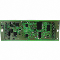
MODULE FOR PPM3-MK2 I/O DRIVER
Manufacturer
Equinox Technologies
Datasheet
1.EQ-SFM-MAX-V1.3.pdf
(85 pages)
Specifications of EQ-SFM-MAX-V1.3
Accessory Type
I/O Driver Module
For Use With/related Products
PPM3-MK2
Lead Free Status / RoHS Status
Lead free / RoHS Compliant
Other names
483-1013


4.5 Programmer / Target System Power Supply Schematic
The schematic shown in fig. 4.5 details the possible power supply scenarios for powering both the
programmer and the Target System.
The key points to note are as follows:
fig. 3.2.1. Explanation of all Power Supply Circuit Schematic labels
#
1
2
3
4
4
5
6
60
•
•
•
•
Item
V_PSU_EXT
GND
V_Target
LK1
I/O Level
Converter /
Driver Circuit
Target Load
Bench Power
Supply
The programmer can be powered from an external power supply (9.0 – 12.0V DC regulated)
via either the ‘DC Jack Socket (J6)’ or the ‘DC Molex Connector (J15)’
The programmer can power the Target System with a user-specified voltage from 3.0 – 5.0V
via the ‘Programmer Controlled Power Supply’.
The programmer ‘Line Driver Circuitry’ must always be powered at the same voltage as the
Target System. This ensures that the logic levels generated from the programmer are
compatible with the logic levels on the Target System.
The external link ‘LK1’ is a virtual link. It simply represents that the Vcc connection between
the programmer and Target Vcc is broken.
Description
•
•
•
•
•
•
•
•
•
This is the voltage applied from an external power supply (9.0 – 12.0V
DC regulated) via either the ‘DC Jack Socket (J6)’ or the ‘DC Molex
Connector (J15)’
This is the common ground of the programmer which is connected to
J6/J15 GROUND and also to the TARGET GROUND via one of the
ISP Headers.
This is the voltage measured between the Vcc and Ground of the
Target System.
This is a virtual link (does not really exist) signifying the cable between
the Programmer TVCC and the Target System Vcc.
If the programmer and Target System are independently powered,
then LK1 must be not fitted i.e. the Target System Vcc wire should not
be connected to the programmer TVCC connection.
This is the circuitry which translates the 5.0V I/O signals from the
programmer ‘Supervisor Microcontroller’ to the Target System voltage
levels.
The supply to the ‘I/O Level Converters’ must be at the same voltage
as the Target System. I.e. if the Target System is powered at 3.3V,
then the ‘I/O Level Converters’ must also be powered at 3.3V.
This is the load presented to the programmer across the PROG_VCC
and GROUND terminals of any ISP Header.
This simply indicates a stable DC power supply with a current limit
facility.
PPM3 MKII Programmer - User Guide - V1.04 - 10
th
May 2008
Related parts for EQ-SFM-MAX-V1.3
Image
Part Number
Description
Manufacturer
Datasheet
Request
R

Part Number:
Description:
MOD PPM3 SPECIAL FUNCTION DRIVER
Manufacturer:
Equinox Technologies

Part Number:
Description:
MODULE FOR PPM3-MK2 I/O DRIVER
Manufacturer:
Equinox Technologies

Part Number:
Description:
CONVERTER KIT, COMMS, RS485
Manufacturer:
Equinox Technologies
Datasheet:

Part Number:
Description:
MOD PPM3 CONN-3 I/O ATMEGA JTAG
Manufacturer:
Equinox Technologies
Datasheet:

Part Number:
Description:
MODULE CONVERTER RS232 TO RS485
Manufacturer:
Equinox Technologies

Part Number:
Description:
MODULE CALCON FOR PPMS-MK2
Manufacturer:
Equinox Technologies
Datasheet:

Part Number:
Description:
ISP PORTABLE PROGRAMMER USB
Manufacturer:
Equinox Technologies
Datasheet:

Part Number:
Description:
ISP PORTABLE HS AVR JTAG USB
Manufacturer:
Equinox Technologies
Datasheet:

Part Number:
Description:
ISP PORTABLE HS AT91SAM7 USB
Manufacturer:
Equinox Technologies
Datasheet:

Part Number:
Description:
ISP PORTABLE USB AT91SAM7 UPGRAD
Manufacturer:
Equinox Technologies

Part Number:
Description:
PORTABLE PRODUCTION ISP HS USB
Manufacturer:
Equinox Technologies
Datasheet:

Part Number:
Description:
ISP MULTI PROJECT AVR JTAG USB
Manufacturer:
Equinox Technologies
Datasheet:

Part Number:
Description:
ISP MULTI PROJECT AT91SAM7 USB
Manufacturer:
Equinox Technologies
Datasheet:

Part Number:
Description:
ISP PRODUCTION PROGRAMMER
Manufacturer:
Equinox Technologies
Datasheet:

Part Number:
Description:
ISP PORTABLE AVR JTAG UPGRAD
Manufacturer:
Equinox Technologies
Datasheet: