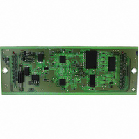
EQ-SFM-MAX-V1.3 Equinox Technologies, EQ-SFM-MAX-V1.3 Datasheet - Page 64

EQ-SFM-MAX-V1.3
Manufacturer Part Number
EQ-SFM-MAX-V1.3
Description
MODULE FOR PPM3-MK2 I/O DRIVER
Manufacturer
Equinox Technologies
Datasheet
1.EQ-SFM-MAX-V1.3.pdf
(85 pages)
Specifications of EQ-SFM-MAX-V1.3
Accessory Type
I/O Driver Module
For Use With/related Products
PPM3-MK2
Lead Free Status / RoHS Status
Lead free / RoHS Compliant
Other names
483-1013
3.5 RS-485 Operation
It is possible to network up to 16 x PPM3 programmers on an RS-485 network and control them from
a single ‘Supervisor PC’ running a single session of the Equinox EQTools or ISP-PRO software. This
scenario requires that each PPM3 programmer is set to ‘RS-485’ operation and that a unique ‘Node
Address’ is set for each programmer. An RS-232 to RS-485 converter is also required to convert the
RS-232 signal from the PC COM port to an optically isolated RS-485 signal suitable for interfacing
with the PPM3’s on the network.
The typical setup is shown in the figure below.
Fig. 3.5 Setup for RS-485 Communications (Multi channel)
For RS-485 operation:
PPM3 MKII Programmer - User Guide - V1.04 - 10
•
•
•
•
•
•
•
•
•
•
•
•
Place the PPM3 programmers side-by-side on a flat surface with the rear panels all facing in
the same direction as detailed in fig. 3.5
For each PPM3 programmer, set the RS-232 / RS-485 DIP Switch (5) to the RS-485 position
For each PPM3 programmer set the required Node Address in the range 0 – 15.
(Each programmer must have unique address. It is customary to start have the first
programmer set to address 0, the next programmer in the chain at address 1 and so on. See
section 3.3 for further details.)
Plug the 9-way RS-232 cable into the port on the RS-232 to RS-485 converter and connect
the other end of the cable to a spare PC COM port.
Plug an RS-485 network cable from one of the RS-485 outputs on the RS-485 converter to the
‘RS-485 Input’ connector (left-hand connector) on the rear panel of the first PPM3 Module.
Plug another RS-485 network cable from the ‘RS-485 Output’ connector (right-hand
connector) on the rear panel of the first PPM3 to the next PPM3 in the chain.
A return RS-485 cable from the last PPM3 in the chain to the RS-485 converter is NOT
required.
Power up the PC.
Plug in and switch on the power supply adaptor supplied with the RS-232/RS-485 convertor
into a spare mains socket.
Power up all PPM3 Programmers.
Launch the ISP-PRO software on the PC and set up the required number of PPM’s within the
software.
Test that all PPM3’s are communicating with the PC at their correct ‘Node Address’. (The
Node Address may be changed while the programmer is powered up).
th
May 2008
53


